YSP20_Users_E.pdf - 第61页
Chapter 2 Basic operations T his chapter explains how to start up the machine and turn it off, as well as basic menus displa yed on the operation screen. W e recommend you read this c hapter while actually operating the …
1-21
1
Part names and functions
n
Table
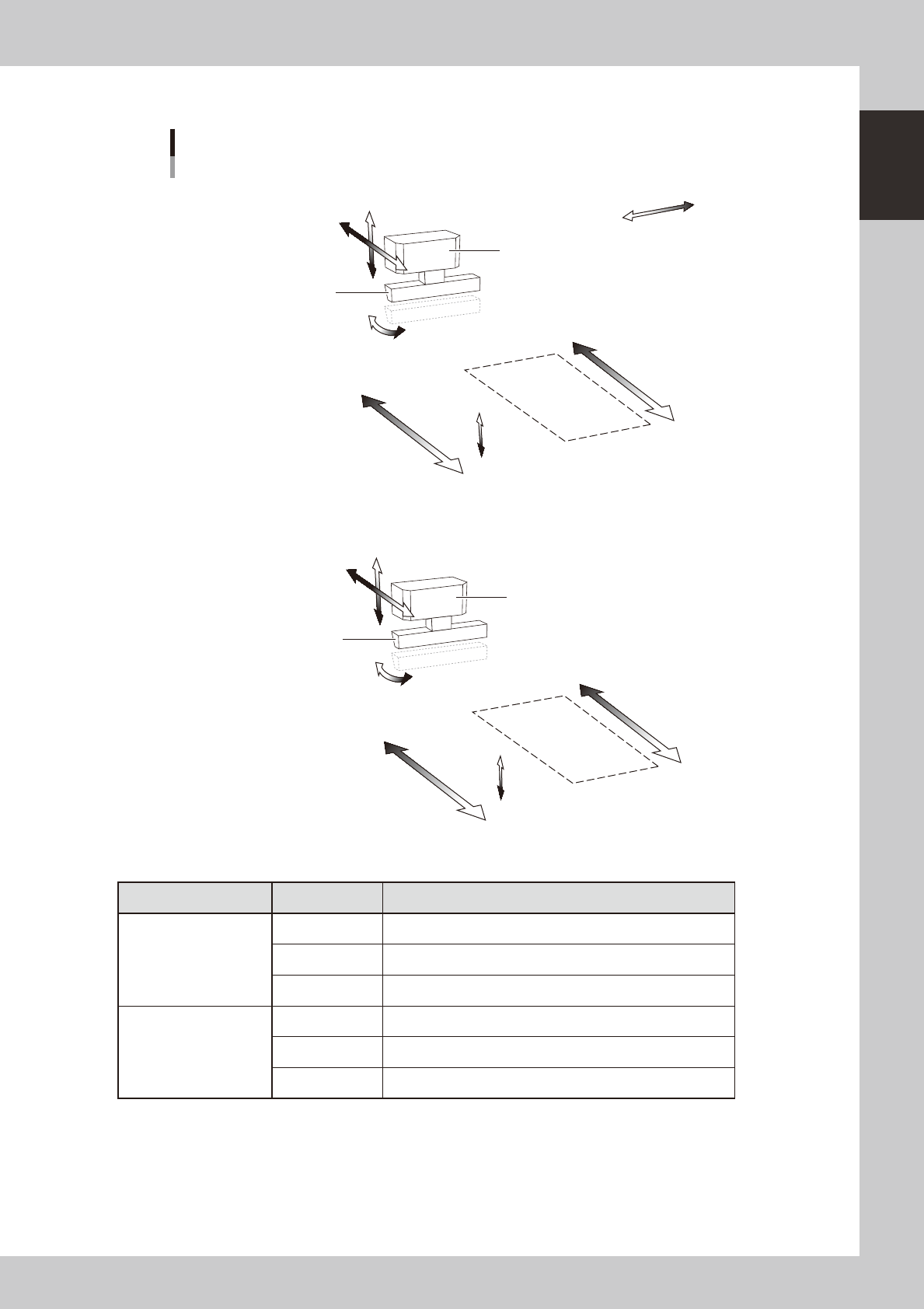
Axis configuration
Squeegee
Squeegee head
Mask
Mask
SRA-axis
SYA-axis
SZA-axis
Plus direction
Minus direction
MYA2-axis
MYA1-axis
MZA-axis
Squeegee
Squeegee head
SRB-axis
SYB-axis
SZB-axis
MYB2-axis
MYB1-axis
MZB-axis
N Table A
N Table B
As viewed from front of RL (right-to-left flow) machine
63125-N3-00
Unit name Axis Function
Squeegee head
SY Moves the squeegee head parallel to the Y-axis.
SZ Moves the squeegee head vertically.
SR Adjusts the squeegee scraper angle. (3S head only)
Printing table
MY1 Moves the mask stage along the Y-axis.
MY2 Moves the mask stage along the R-axis.
MZ Adjusts the mask stage along the Z-axis.

Chapter 2 Basic operations
This chapter explains how to start up the machine and turn it off, as well as basic menus displayed on the operation screen.
We recommend you read this chapter while actually operating the machine as instructed.
Contents
1.
Canceling emergency stop and clearing an error
2-1
1.1 Canceling emergency stop 2-1
1.2 Clearing an error 2-2
1.3 Typical errors and troubleshooting 2-3
2. Starting and stopping the machine 2-9
2.1 Inspecting before operation 2-10
2.2 Starting the machine 2-11
2.3 Turning off the machine 2-13
5
5
6
2-1
2
asic operations
1. Canceling emergency stop and clearing an error
The following explains how to cancel emergency stop and clear errors.
1.1 Canceling emergency stop
When the machine is in emergency stop, the red signal lamp on the top of the machine is lit and the red
"EMERGENCY STOP" sign is displayed in the status area of the operation screen. Follow these steps to cancel
emergency stop.
1
Release the emergency stop button.
When the emergency stop button is pressed (turned on), turn it clockwise to release it. There are two
emergency stop buttons on the YSP main unit: One is on the operation panel (front upper right) and the
other is at the upper right on the rear panel.
TIP
When emergency stop was triggered by a safety interlock switch, first eliminate the cause of emergency stop and
then cancel it.
2
Check safety.
Before continuing the procedure, check the surrounding area for safety.
3
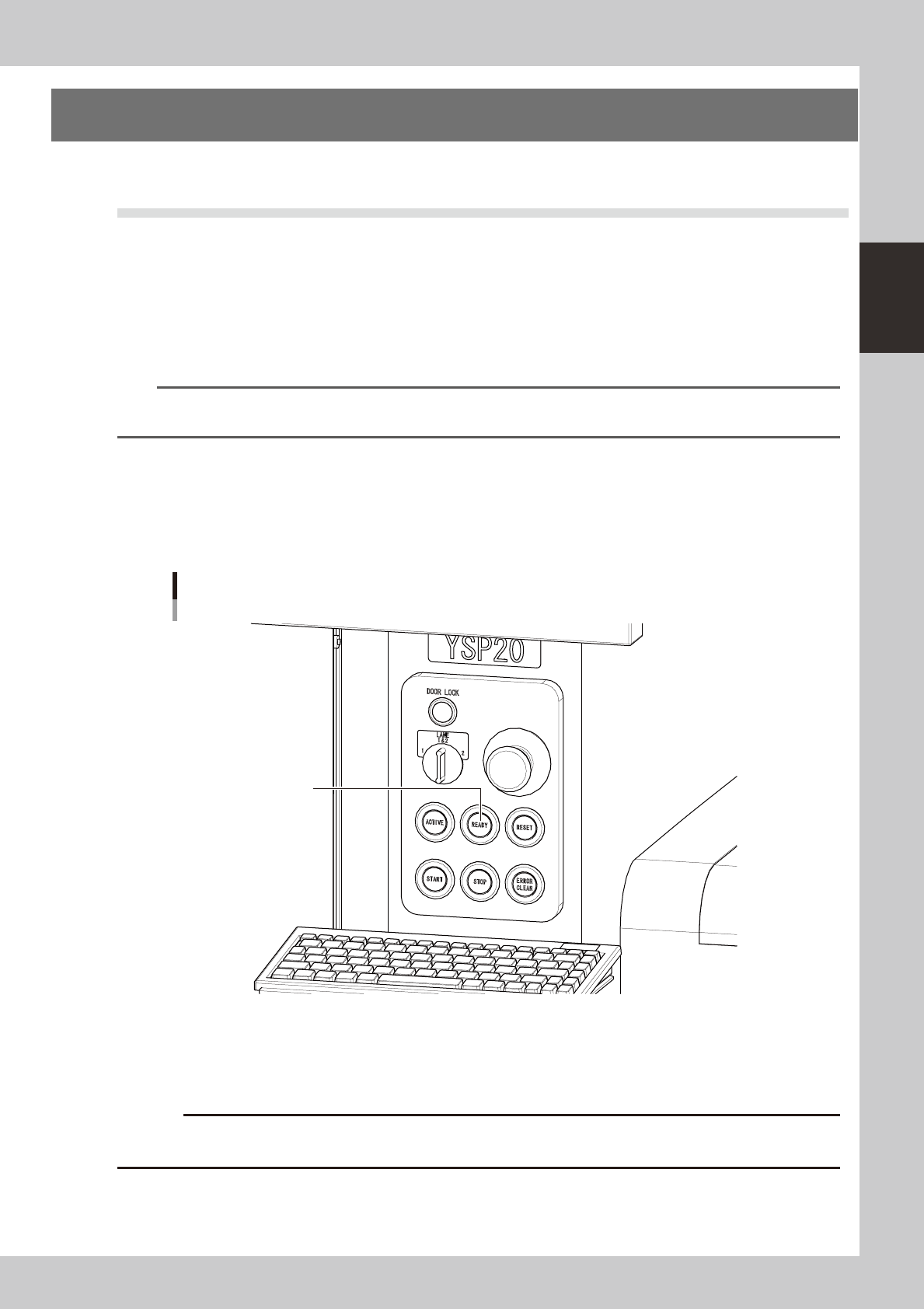
Press the [READY] button on the operation panel.
Pressing the [READY] button turns on the servomotors.
[READY] button
[READY] button
63201-N3-00
4
Check the signal light and screen display.
Check that the red signal lamp is off and the emergency stop sign in the upper left (status area) of the
operation screen is now off.
c
immediately in case of emergency.