YSP20_Users_E.pdf - 第144页
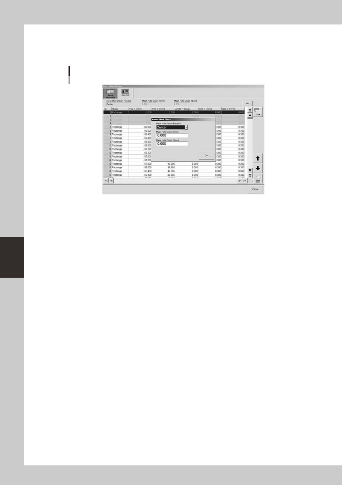
5-18 5 Creating and setting the data l Mask aper ture coordinate setting When you press the [Detail] button on the [Print]-[Mask] tab, the following dialog box appears for setting the mask aperture coordinates. [Mask Hol…
5-17
5
Creating and setting the data
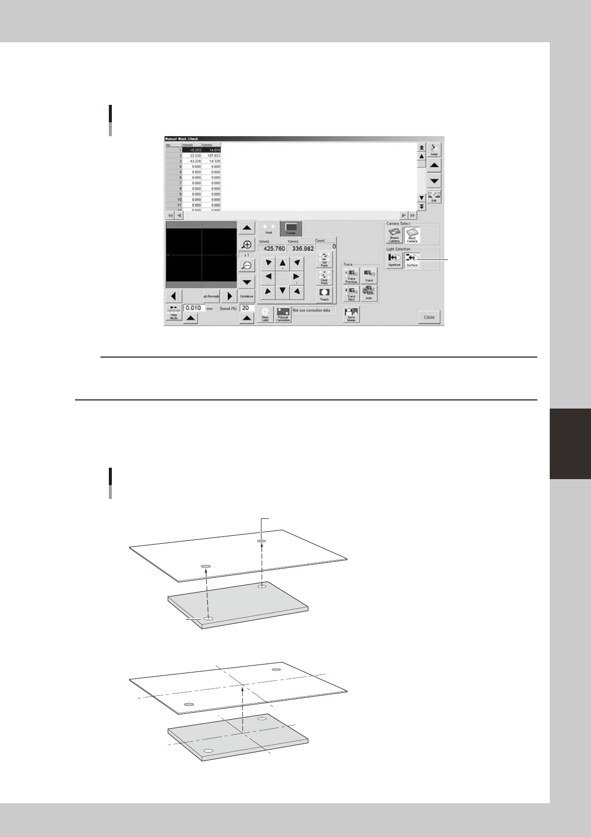
To set the lighting for inspecting excess solder and flux spreading to the backside of the mask, press the [Light] button
while the [Surface] button is depressed. You can then change to an optimum lighting level on the lighting setup window.
In either case, closing the window automatically stores the changes you made into the board data.
"Teach/Trace" window for visual mask check
[Surface] button
[Surface] button
64521-N3-10
n
NOTE
By storing the visual check lighting levels for the mask aperture and backside, you can switch to each lighting level by
just pressing the [Aperture] button for the mask aperture visual check or the [Surface] button for the mask backside
visual check.
l
Aligning the board and mask positions
When the board and mask each have positioning marks on both sides, the following two positioning methods can be
used.
Mask mark
N Board and mask mark positions are on the same coordinates
N Board and mask mark positions are on different coordinates
Board mark
Positioning marks on Board and mask
Image processing is first performed to detect
the amount of position shift with reference to
the theoretical mark positions on the Board and mask.
Based on this, the Board and mask positions
are determined so that their marks are exactly aligned.
Image processing is first performed to detect the
amount of position shift with reference to the
theoretical mark positions on the Board and mask.
Based on this, the Board and mask positions are
determined so that their centers are exactly aligned.
Then, angular positioning of the Board and mask is
corrected respectively, so that a line connecting
the two marks is aligned with the line connecting
the theoretical positions of the marks.
63513-N3-00
5-18
5
Creating and setting the data
l
Mask aperture coordinate setting
When you press the [Detail] button on the [Print]-[Mask] tab, the following dialog box appears for setting the mask
aperture coordinates.
[Mask Hole] tab
64554-N3-10
This function is available only for machines equipped with an optional print inspection camera.
For more information, refer to "2.3 Using the mask scan function" in Chapter 2 of the separate option manual "Solder-
print inspection".
5-19
5
Creating and setting the data
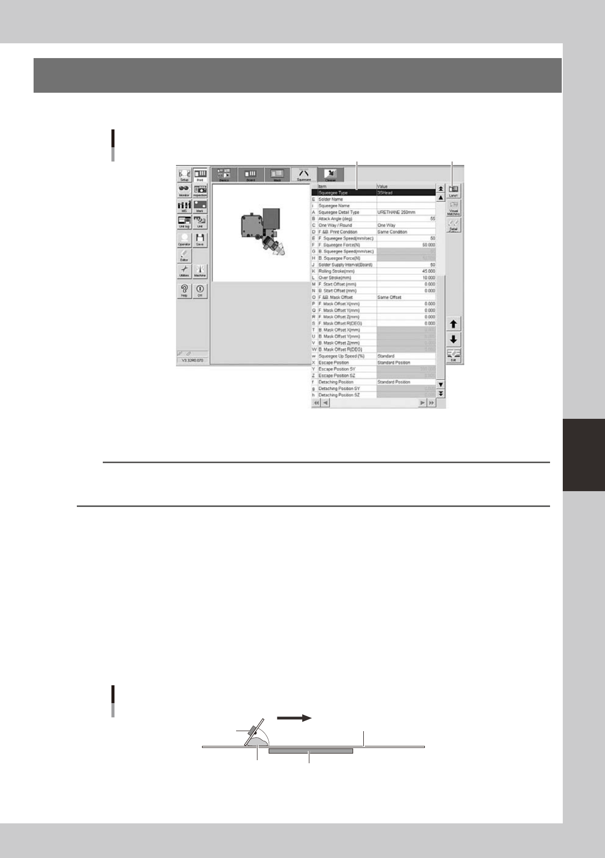
5. Squeegee data setting
The following parameter items can be checked and edited on the [Print]-[Squeegee] tab.
[Print]-[Squeegee] tab
1 [Lane] button
64522-N3-10
1: Squeegee Type
Select "3S Head” when using the 3S squeegee head. When using an optional double squeegee, select "Double Squeegee".
TIP
The squeegee type has been set in the machine data prior to shipment according to the machine specifications. So
the same squeegee type as set in the machine data must be selected here. If not the same squeegee type, an error
is issued.
E: Solder Name
Enter the name or comment on the solder to be used. You can leave this field blank.
i: Squeeges Name
Enter the name or comment on the squeeges to be used. You can leave this field blank.
A: Squeegee Detail Type
Specify the squeegee type and size when the squeegee type is set to "3S Head” or “Double Squeegee".
B: Attack Angle (deg.)
This parameter is available only when the squeegee type is set to "3S Head". (This parameter does not appear when the
squeegee type is set to "Double Squeegee".)
Set the angle formed between the 3S squeegee scraper and the mask surface in order to print solder most efficiently. The
setting range is from 40 to 65 degrees. (Default setting is 55 degrees.)
Attack angle (3S head only)
Solder
Attack angle (scraper angle)
Board
Mask
3S squeegee scraper
Printing direction
63535-N3-00
C: One Way/Round
Select whether to print solder in one direction or in both directions.