TR7500_Series_Software_v29_En.pdf - 第104页
Test Research Inc. 82 TR7500 Series User Guide – Software v.2.9.0 3.4.9 Non CAD I n terface Update for v.2.4 In v.2.4, the interface ha s been changed t o the foll o wing figure. All comma nds and functions are the same …
Test Research Inc.
TR7500 Series User Guide –Software v.2.9.0 81
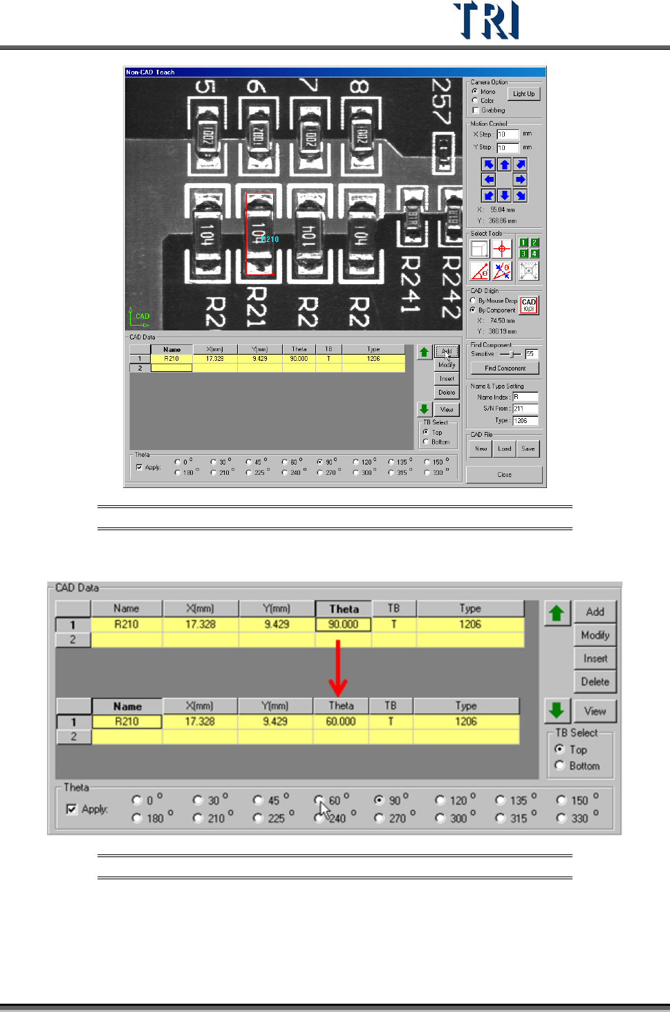
Figure 138: Set Theta Data When Using Box Tool
Select a [Theta] field and select an angle to change the data directly.
Figure 139: Edit Theta Angle Directly
Test Research Inc.
82 TR7500 Series User Guide –Software v.2.9.0
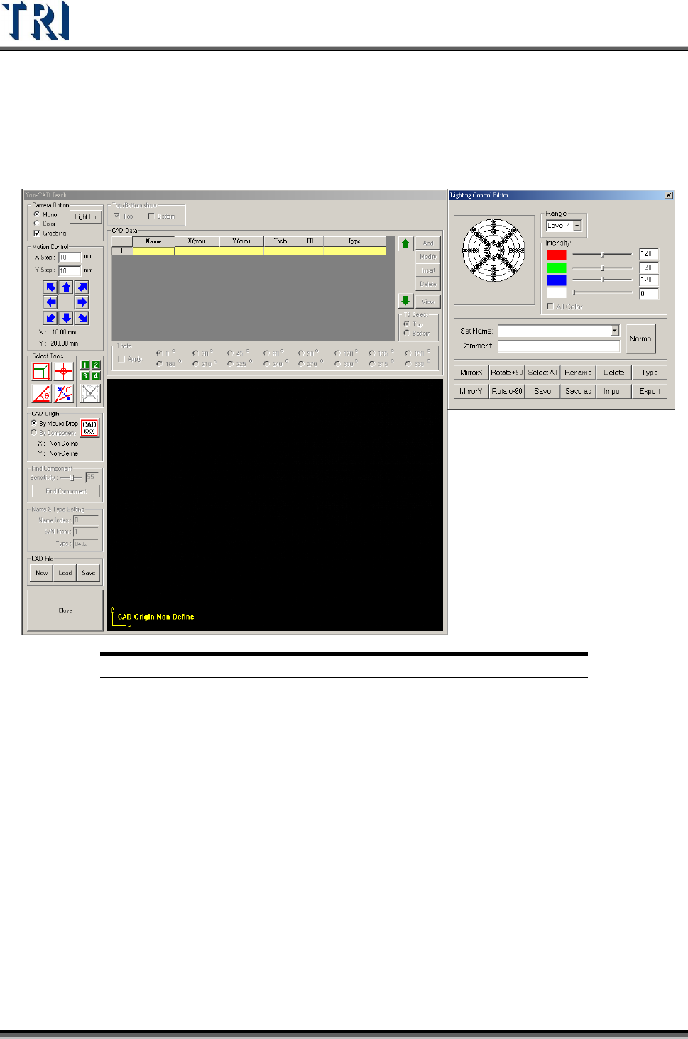
3.4.9 Non CAD Interface Update for v.2.4
In v.2.4, the interface has been changed to the following figure. All commands and functions
are the same as in previous versions unless otherwise noted.
Figure 140: Non-CAD Teach v.2.4 Interface
3.4.10 Multi Panel Alignment Setting
If it is necessary to inspect more than one panel at a time, this function can be
enabled. Under [Auto Mode], the system will inspect all panels in sequence then
send all panels out. Under [Confirm Mode], after finishing inspecting one panel, the
operator has to confirm the panel before the system will inspect the next panel. The
panels will be sent to exit after all they are all tested.
It is important to avoid the variation of gap between panels. If necessary, enlarge
the search range of the fiducial marks.
The detailed settings are shown in the following figure.
Test Research Inc.
TR7500 Series User Guide –Software v.2.9.0 83
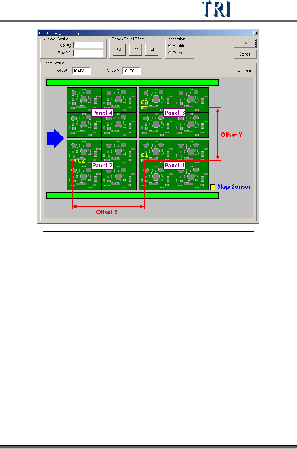
Figure 141: Multi-Panel Algorithm Setting
[Col(X)] – Set the number of columns of X-axis boards.
[Row(Y)] – Set the number of rows of Y-axis boards.
[Teach Panel Offset] – This function helps to calculate the [Offset X] and [Offset Y].
C1, C2 and C3 must be the same component. After clicking on [C1], a training
window is presented. Move the cross or box tool to get the C1 location then press
[OK] to finish finding C1. Then press [C2] and [C3] in sequence to find the position
of C2 and C3. When finishing, the system will calculate the value and input the
[Offset X] and [Offset Y] automatically.
[Inspection] – Selecting [Enable] will start this function.
[Offset Setting] – Input the Offset of X axis and Y axis directly instead of using the
teaching operation.
3.4.11 Placer Check
Load the .AOI file that includes the placer information, then the system will compare the
component information in the .PRE with the data in the .AOI file. System will replace the
placer information of the components in the .PRE file only.