TR7500_Series_Software_v29_En.pdf - 第294页
Test Research Inc. 272 TR7500 Series User Guid e –Softwa re v.2.9.0 Figure 457 : Adjust Multi-Fu nction Windo w Step2. Select the copy rules. [By Board] means c opy the setting to related multi-b oar d FOVs. Selectin g t…
Test Research Inc.
TR7500 Series User Guide –Software v.2.9.0 271
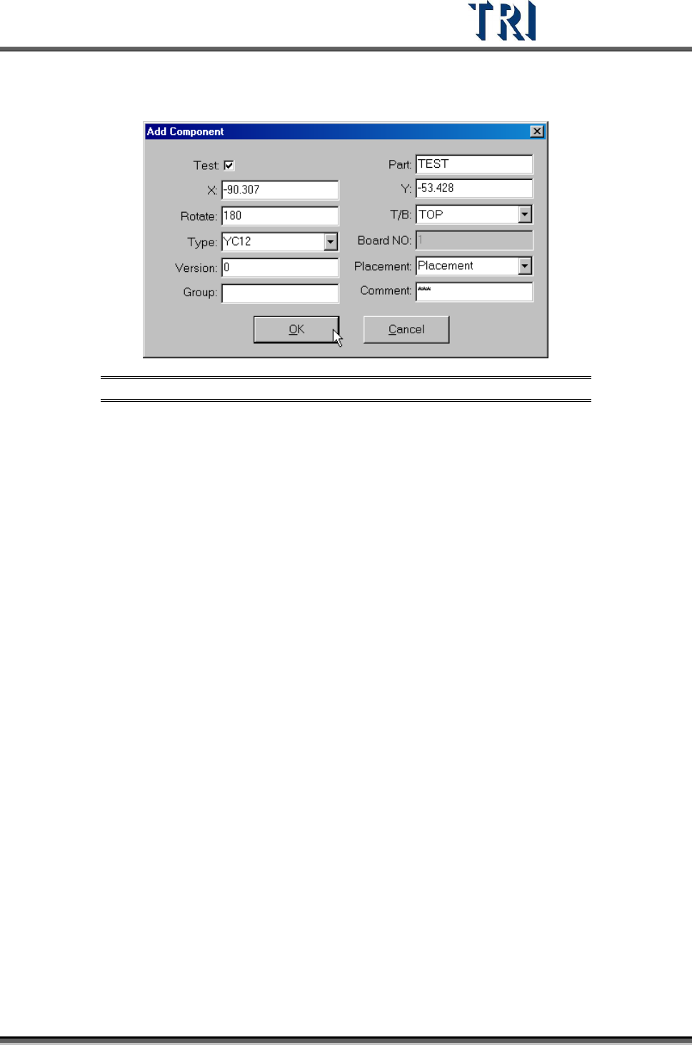
Step2. Press [New Comp.] button. Input all component information except the X and Y
axis coordinates.
Figure 456: Add Component Dialog
Step3. Press [OK] to finish the setting.
Step4. Press [Merge] to merge the library.
Step5. Capture the FOV images again.
Step6. Enter [Train] dialog to edit the component.
11.9.3.2 Reset Win.
Reset the size and position of the multi-function window.
11.9.4 Warp Setting
11.9.4.1 SetWarp/DelWarp
Set a [Warp] for the current FOV. Move the multi-function window to a suitable position and
adjust the size. Then press [SetWarp] to set a warp window. When the check box is selected,
[Warp] will be inspected with Method 1. If the check box is not selected, [Warp] will be
inspected with Method 2.
Only one [Warp] setting is allowed per FOV. After [Warp] is set, the character on the button
changes to [DelWarp]. Select [DelWarp] to delete the [Warp] setting.
Setting Steps
Step1. Adjust the position and size of the multi-function window to suit the object.
Test Research Inc.
272 TR7500 Series User Guide –Software v.2.9.0
Figure 457: Adjust Multi-Function Window
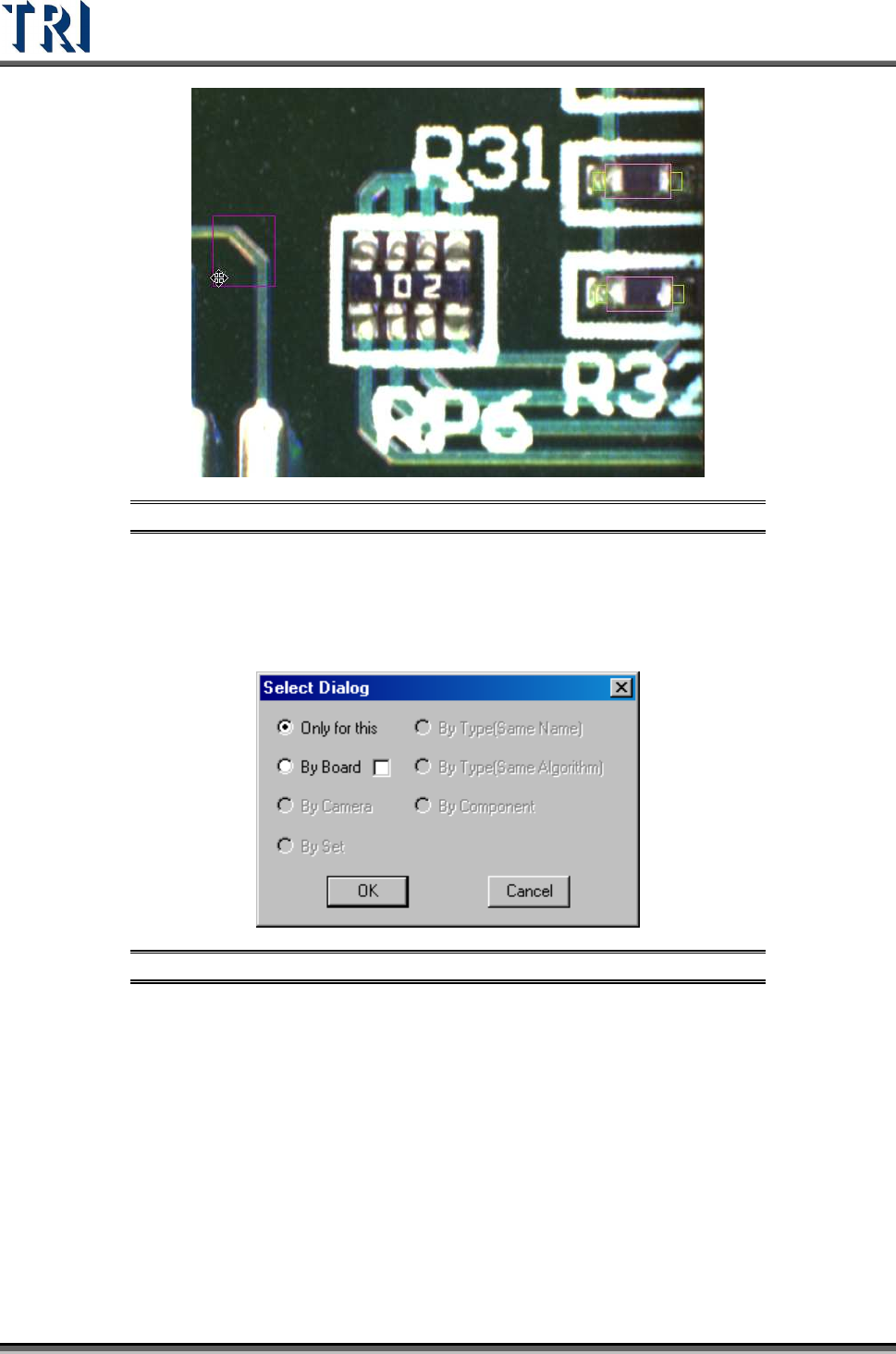
Step2. Select the copy rules. [By Board] means copy the setting to related multi-board
FOVs. Selecting the check box means the inspection boxes will be moved a
relative distance according to the [Warp] position setting when copying the
[Warp] to multiple boards on the same panel.
Figure 458: Select Warp Copy Rules
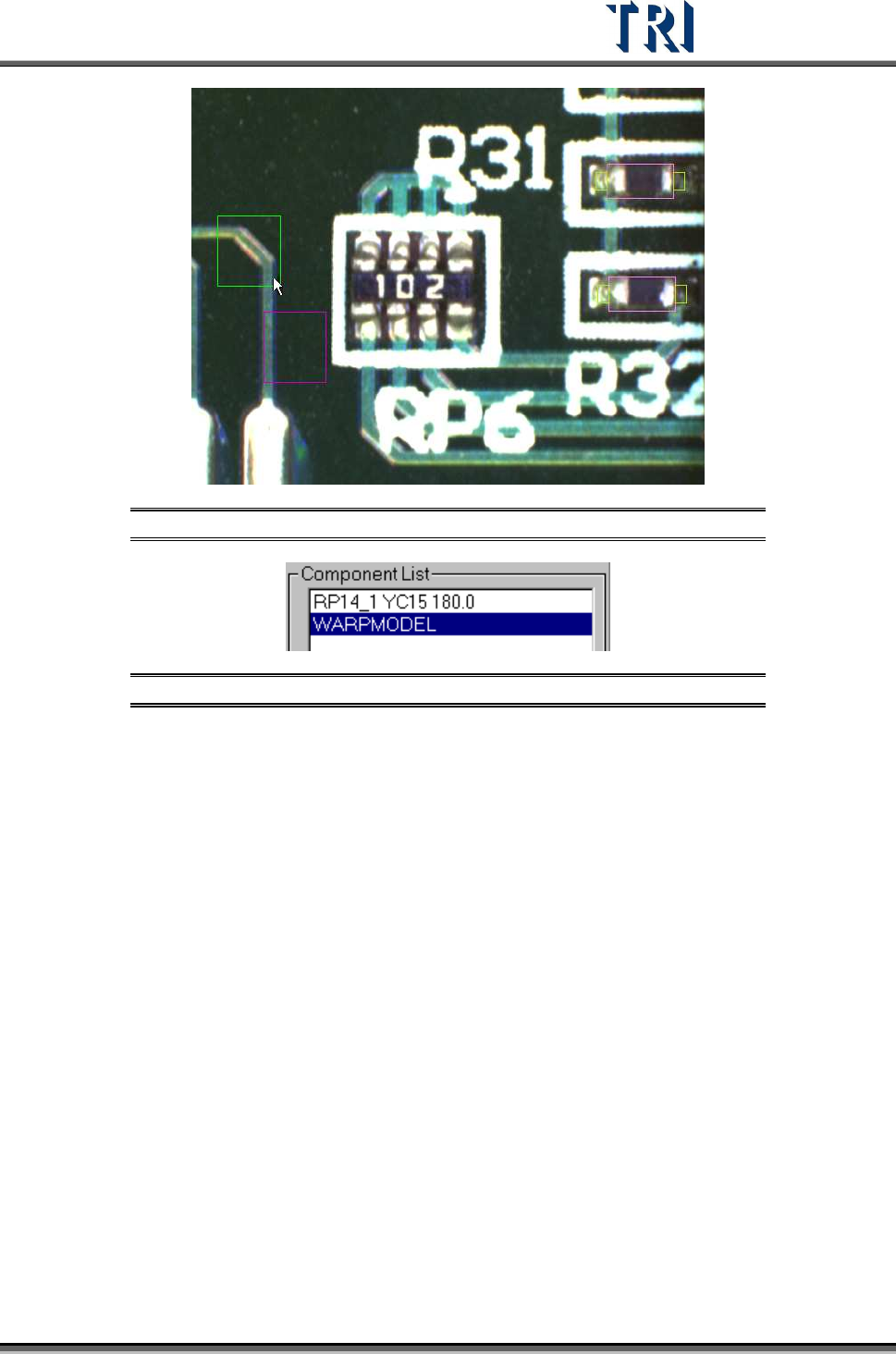
Step3. When finished setting there is a warp on the FOV image and a [WARPMODEL]
component in the component list.
Test Research Inc.
TR7500 Series User Guide –Software v.2.9.0 273
Figure 459: Warp Set on FOV Image
Figure 460: WarpModel in Component List