TR7500_Series_Software_v29_En.pdf - 第292页
Test Research Inc. 270 TR7500 Series User Guid e –Softwa re v.2.9.0 Create the other linke d boxes at the sa me time. If there are so m e inspecti on boxes that are linked with the object box es, the linked boxes w i ll …
Test Research Inc.
TR7500 Series User Guide –Software v.2.9.0 269
11.9.2.9 Add N Box
Select a box first as the standard image and the system will search in the multi-function
window to find similar images and add inspection boxes.
Setting Steps
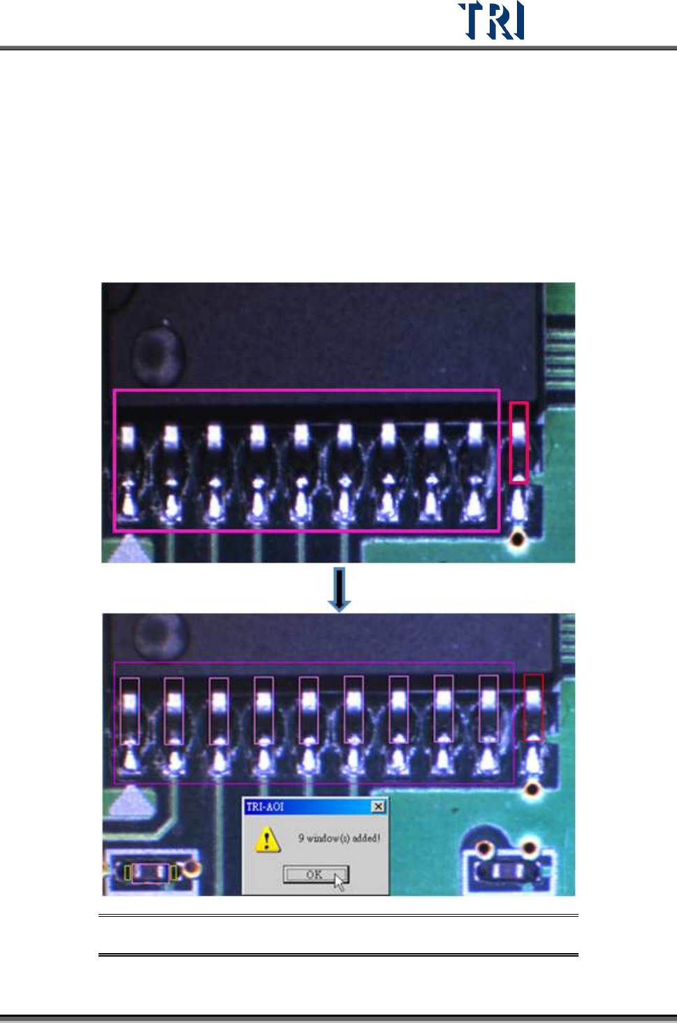
Step1. Select an inspection box as the standard and adjust the multi-function window
to cover the object area.
Step2. Press [Add N Box] to finish the setting.
Figure 453: Select Inspection Box (Red) & Adjust Multi-Function Window
(Purple)
Test Research Inc.
270 TR7500 Series User Guide –Software v.2.9.0
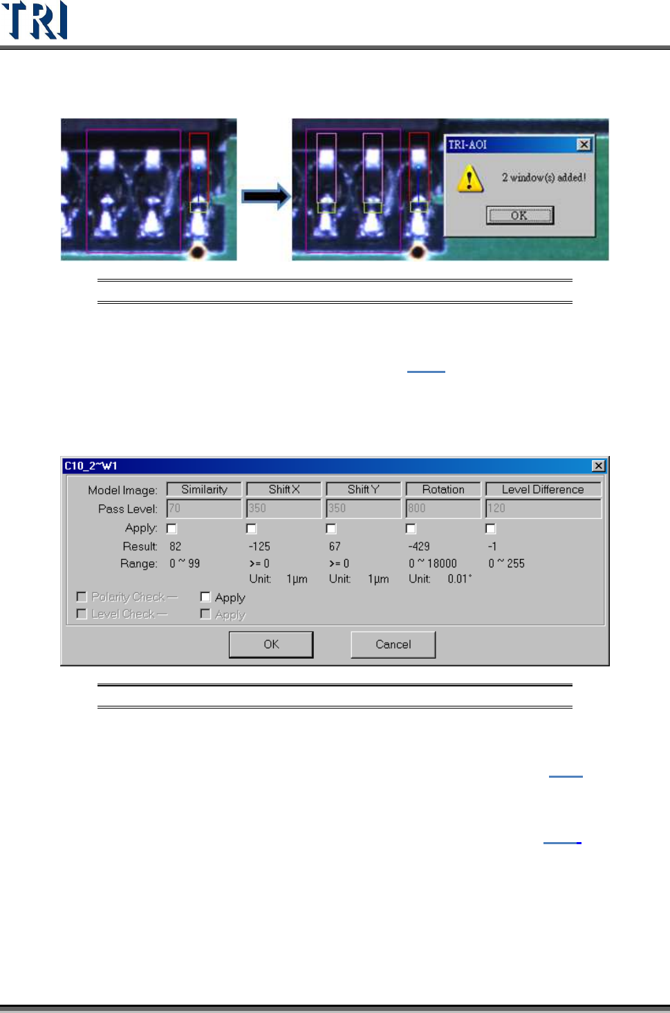
Create the other linked boxes at the same time. If there are some inspection boxes that are
linked with the object boxes, the linked boxes will be created at the same time.
Figure 454: Add Linked Inspection Windows
11.9.2.10 Set Logic
Set the Logic between windows. See more about logic in 8.7.1.
11.9.2.11 Setting
Set the pass level for selected inspection window.
Figure 455: Inspection Window Pass Level
11.9.2.12 Link
Assign windows that are parents and children to link. See more about [Link] in 8.2.2
11.9.2.13 UnLink
Press [Unlink] to break the link between windows. See more about [Unlink] in 8.2.3.
11.9.3 New Comp & Reset Win.
11.9.3.1 New Comp.
Add a new component in the project. The component data will also be added in the AOI file..
Setting Steps
Step1. Move the multi-function window to the center of the component.
Test Research Inc.
TR7500 Series User Guide –Software v.2.9.0 271
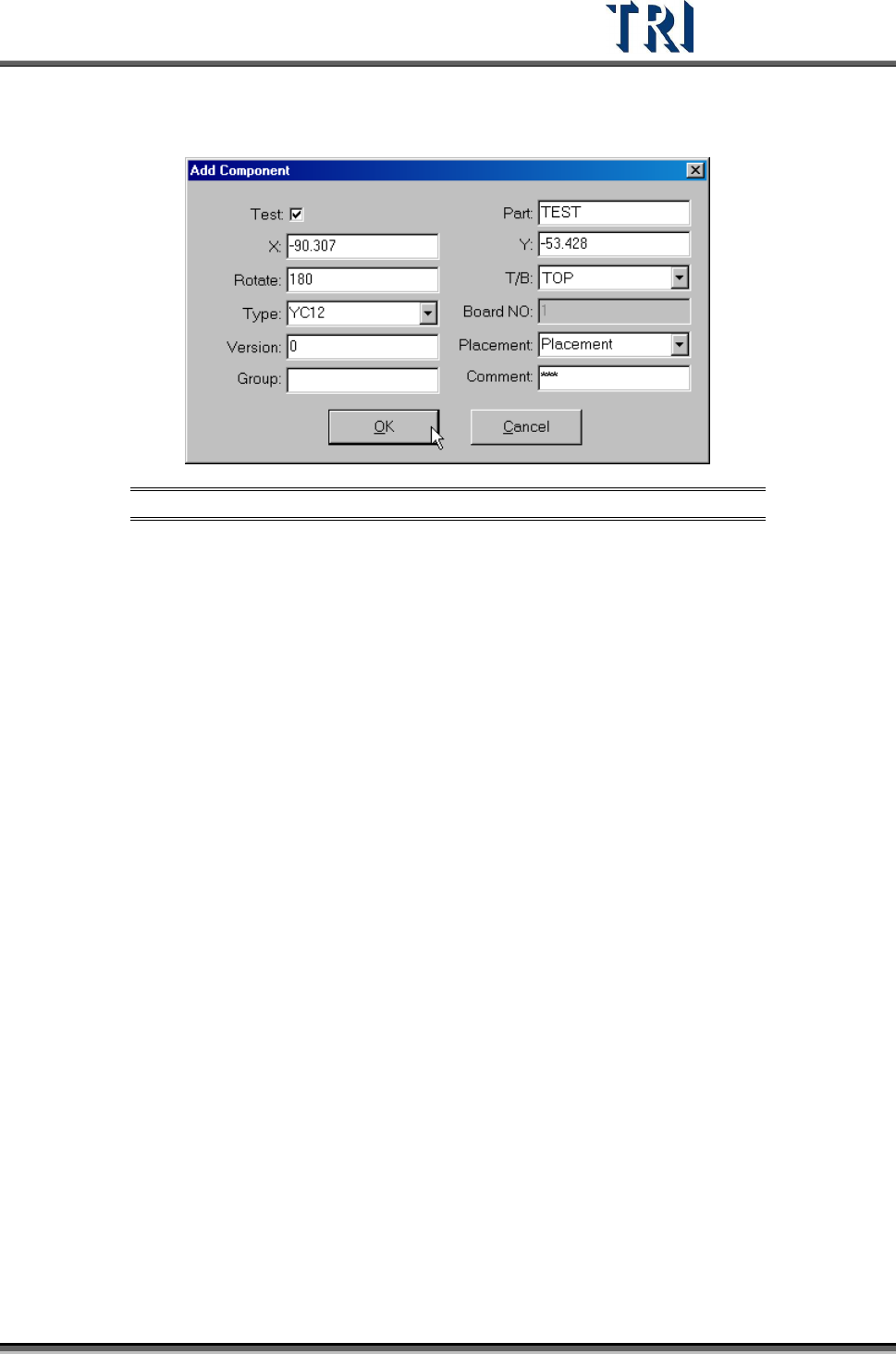
Step2. Press [New Comp.] button. Input all component information except the X and Y
axis coordinates.
Figure 456: Add Component Dialog
Step3. Press [OK] to finish the setting.
Step4. Press [Merge] to merge the library.
Step5. Capture the FOV images again.
Step6. Enter [Train] dialog to edit the component.
11.9.3.2 Reset Win.
Reset the size and position of the multi-function window.
11.9.4 Warp Setting
11.9.4.1 SetWarp/DelWarp
Set a [Warp] for the current FOV. Move the multi-function window to a suitable position and
adjust the size. Then press [SetWarp] to set a warp window. When the check box is selected,
[Warp] will be inspected with Method 1. If the check box is not selected, [Warp] will be
inspected with Method 2.
Only one [Warp] setting is allowed per FOV. After [Warp] is set, the character on the button
changes to [DelWarp]. Select [DelWarp] to delete the [Warp] setting.
Setting Steps
Step1. Adjust the position and size of the multi-function window to suit the object.