TR7500_Series_Software_v29_En.pdf - 第311页
Test Research Inc. TR7500 Series User Guide – Software v.2.9.0 289 11.9.14 Change FOV 11.9.14 .1 Previous Review the previous FOV. 11.9.14 .2 Next Review the next FOV. 11.9.14 .3 OK Close the [Train] dial og. 11.9.15 Inf…
Test Research Inc.
288 TR7500 Series User Guide –Software v.2.9.0
11.9.13 Find FOV by Type/Name
11.9.13.1 Type
Input or select a type as a condition.
11.9.13.2 Name
Input or select a name as a condition.
11.9.13.3 Trained
Select to set trained component as a condition.
11.9.13.4 UnTrained
Select to set untrained component as a condition.
11.9.13.5 Test
Select to set test component as a condition.
11.9.13.6 UnTest
Select to set untest component as a condition.
11.9.13.7 Single Void/Pin
Select to find the single [Void] or [Pin] window in order to find the FOV that needs to add
[Warp].
11.9.13.8 Previous
Clicking on this causes the system to find the previous FOV according to the above
conditions.
11.9.13.9 Next
Click on this and the system will find the next FOV according to the above conditions.
Test Research Inc.
TR7500 Series User Guide –Software v.2.9.0 289
11.9.14 Change FOV
11.9.14.1 Previous
Review the previous FOV.
11.9.14.2 Next
Review the next FOV.
11.9.14.3 OK
Close the [Train] dialog.
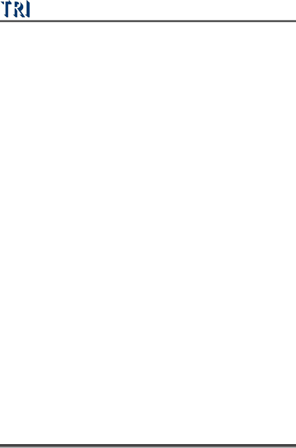
11.9.15 Information Bar
Figure 479: Information Bar
Referring to the figure above, [W] is the horizontal width of the control box. The first number
(100) is pixels, and the second (1.50) is the unit of the measurement in millimeters. [H] is the
vertical height of the control box and [Di] is the diagonal length.
The [Info] section displays the width and height of the inspection box.
The field at the bottom displays first, the [FOV Image Label] number (F1-3-6). [Toplight A] is
the lighting method of the FOV. The last numbers (6-3) refers to board 6 image 3.
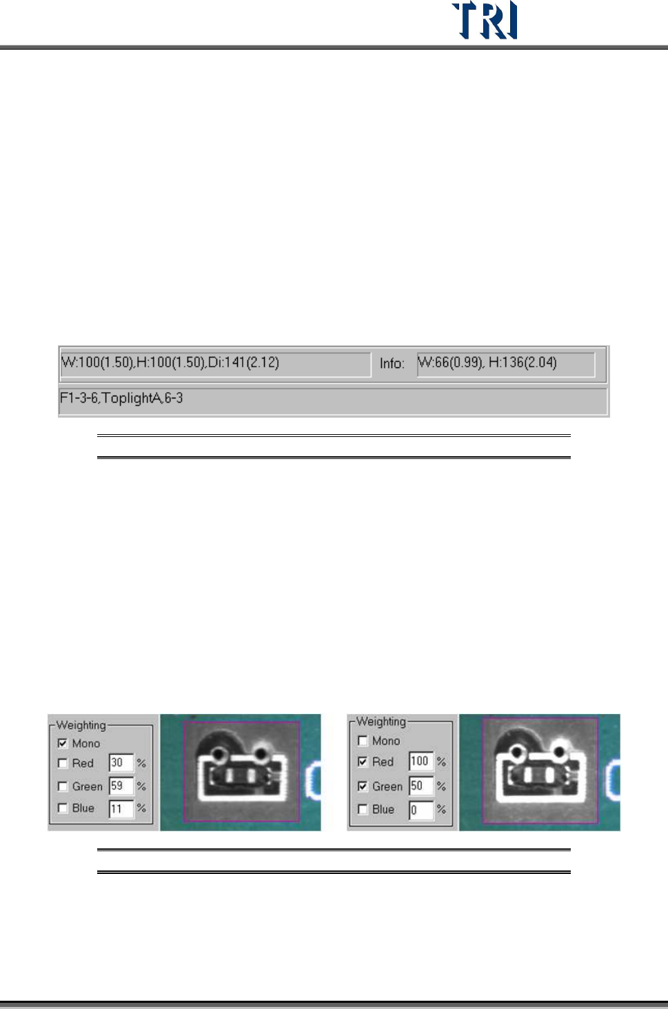
11.9.16 Weighting
After checking [Mono] or [RGB], the image in the multi-function window displays according to
the setting. This is for user's reference.
Figure 480: Examples of Weighting: Mono (left) & RGB
Test Research Inc.
290 TR7500 Series User Guide –Software v.2.9.0
12 I
NSPECTION
D
IALOG
F
UNCTION
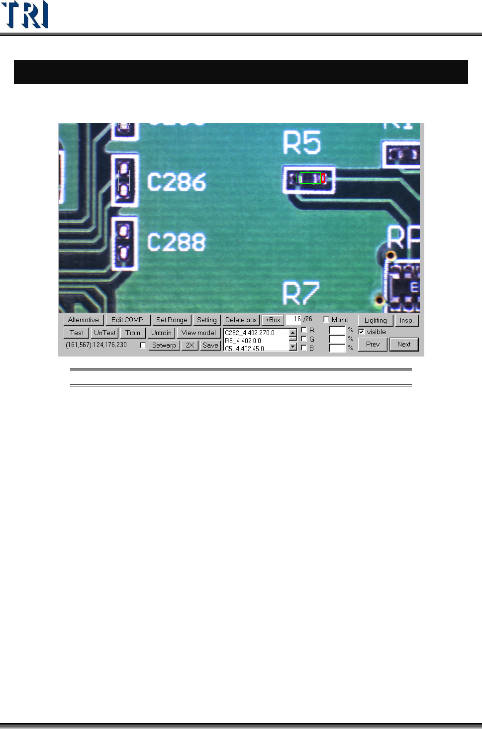
12.1 Image Diagram Functions
Figure 481: Image Diagram Functions
[Alternative ]– Add an alternative to a component.
[Edit COMP]. – Edit component name and angle.
[SetRange] – Set search range for an inspection box.
[Setting] – Set the pass level.
[Delete box] – Delete selected box.
[+Box] – Add one box to selected component.
[Test/UnTest] – Set selected box as test or untest.
[Train/UnTrain] – Train inspection or set trained box as untrained.
[View model] – Review the standard images
[Setwarp/Delwarp] – Set or delete [Warp].
[2X] – Show the double-sized FOV image. The display area is the multi-function
location and the image is reviewed for test.
[Save] – Save the image to the folder.
[Lighting] – Change the lighting for inspection.
[Insp.] – Inspect the current FOV.
[Visible] – Selecting this displays the inspection boxes.