TR7500_Series_Software_v29_En.pdf - 第98页
Test Research Inc. 76 TR7500 Series User Guide – Software v.2.9.0 and the origin is marke d as blue icon. T here are tw o ways to set origin. Figure 132 : CAD Origin Not Defined Warn ing Figure 133 : CAD Origin By Mouse …
Test Research Inc.
TR7500 Series User Guide –Software v.2.9.0 75
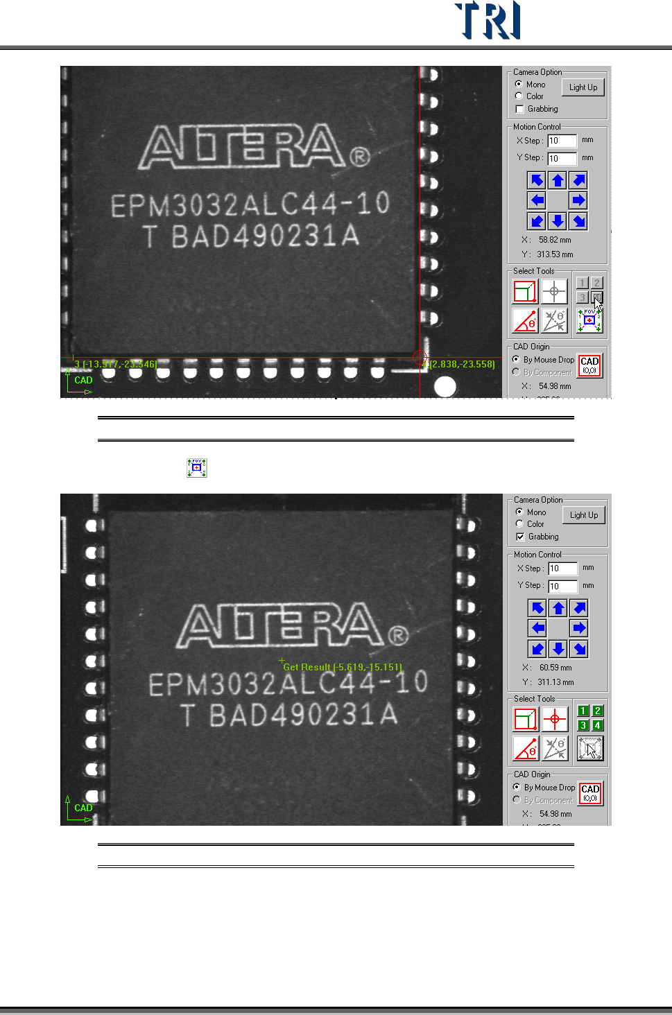
Figure 130: Large Component Tool, Step 2
Step3. Press and the system will calculate the component center automatically.
Figure 131: Large Component Tool, Result
Step4. Press [Add] to add the component after input relevant information.
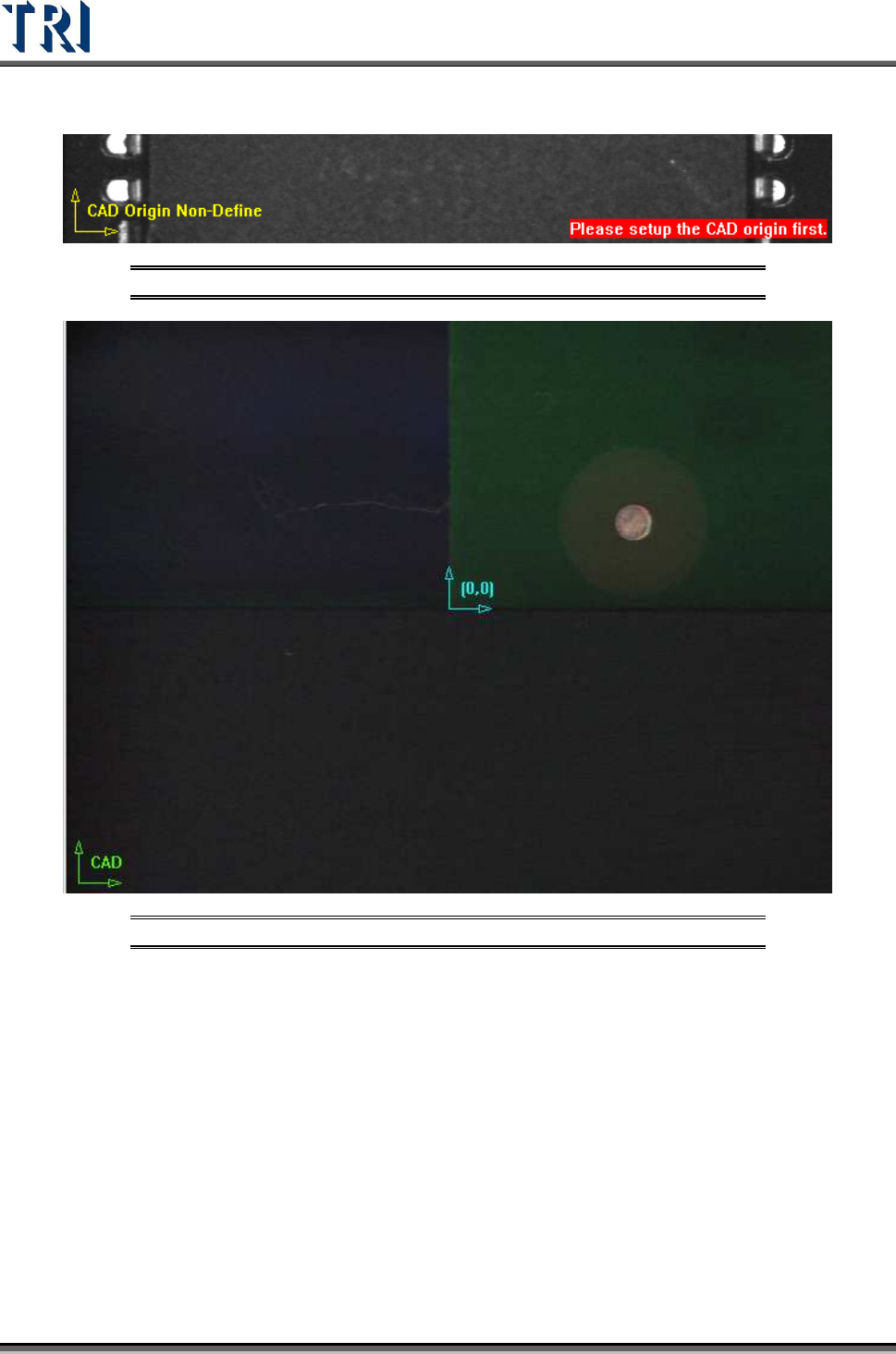
(4) [CAD Origin] - Set the origin first for reference before building the component CAD
data. A yellow right angle icon will flash at the lower-left corner to show the origin has
not been set yet. If the origin has already been established the icon is changed to green
Test Research Inc.
76 TR7500 Series User Guide –Software v.2.9.0
and the origin is marked as blue icon. There are two ways to set origin.
Figure 132: CAD Origin Not Defined Warning
Figure 133: CAD Origin By Mouse Click
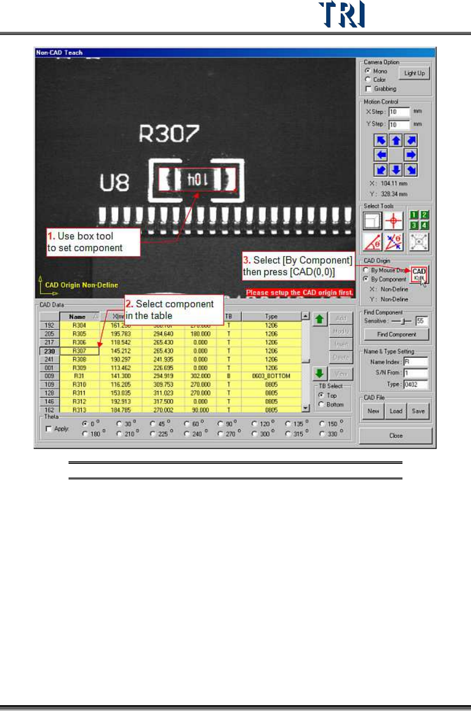
[By Mouse Drop] - Use this method when editing a new CAD file. Move box or
cross line tool to the position which you want to set on then press [CAD(0,0)] and
the system will record the coordinates of the origin.
[By Component] - Use this method when loading an existing AOI file for
continuous editing. Select a component in the component list field and move a tool
to the component center. Press [CAD(0,0)] button then the system will record the
coordinates of the origin.
Test Research Inc.
TR7500 Series User Guide –Software v.2.9.0 77
Figure 134: Non-CAD Teach Procedure 1
(5) [Find Component] - Use this function to create components which are similar to a
standard image.