TR7500_Series_Software_v29_En.pdf - 第285页
Test Research Inc. TR7500 Series User Guide – Software v.2.9.0 263 Figure 439 : Confirm Reloca te & Train Align Window 11.9.2. 4 +Alternative Add an alternative image to [Mi ssing ] or [Missi ng Polarity] wi ndow. Ad…
Test Research Inc.
262 TR7500 Series User Guide –Software v.2.9.0
[By Type (Same Name)] –The component with same type will be applied at the
inspection box with same window name.
[By Type (Same Algorithm)] –The component with same type will be applied at
the same kind of inspection box.
[By Component] – Apply to all of the same kind of inspection boxes on this
component.
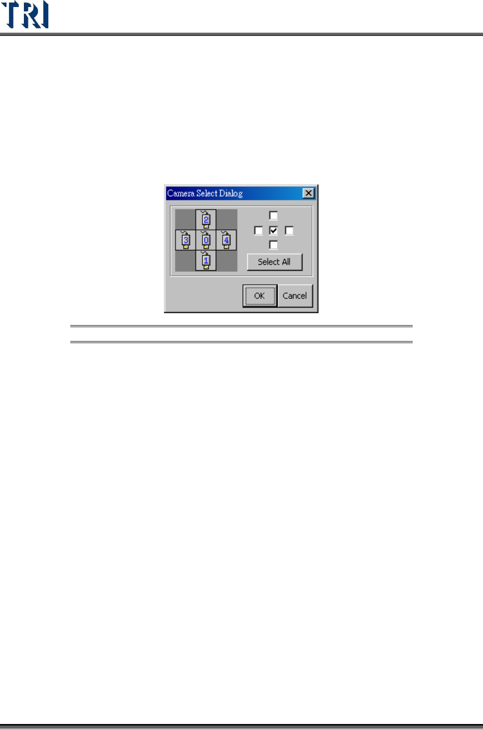
Step4. Select the camera to apply.
Figure 438: Camera Select Dialog
Step5. The system will search the range and measure the symmetrical arrangement of
frame position
11.9.2.2 Train
Train the selected components. It shows that applies mechanically standard image, the
parameter and other settlement on this component to train, the system will only inspect in
having component trained.
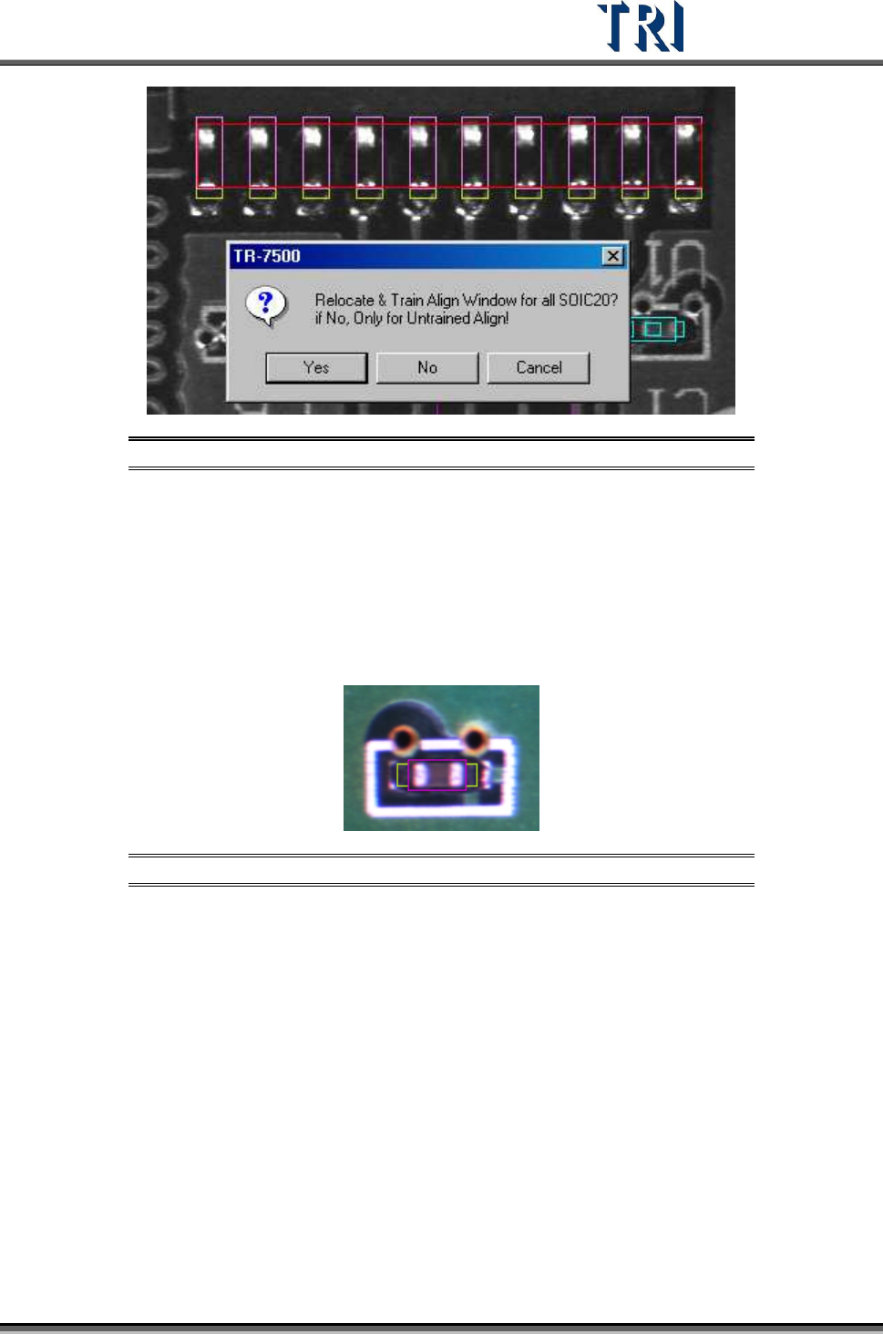
11.9.2.3 Autoalign
The system will automatically relocate the align box according to the selected and trained
align window. Select a trained align window and press [Autoalign] to relocate the other
inspection boxes with the same type. Only if the similarity is high enough can the aligned
window be trained.
[Align] is an auto positioning system that records the X, Y coordinates for graying. When you
[Train], the graying in the X (or Y) direction should be 10 pins but the search returns only 1 –
9 pins in alignment because there is no way to predict the unknown (e.g. more than 11 pins).
Therefore, when doing [Align] fixed positioning, select more pins for searching and matching
Only untrained align windows are qualified for the [Auto alignment] function.
Test Research Inc.
TR7500 Series User Guide –Software v.2.9.0 263
Figure 439: Confirm Relocate & Train Align Window
11.9.2.4 +Alternative
Add an alternative image to [Missing] or [Missing Polarity] window. Adding an alternative
image adds a standard image for the component. The box will be regarded as pass if one or
more images are passed. The number of the alternative images is not limited.
Setting Steps
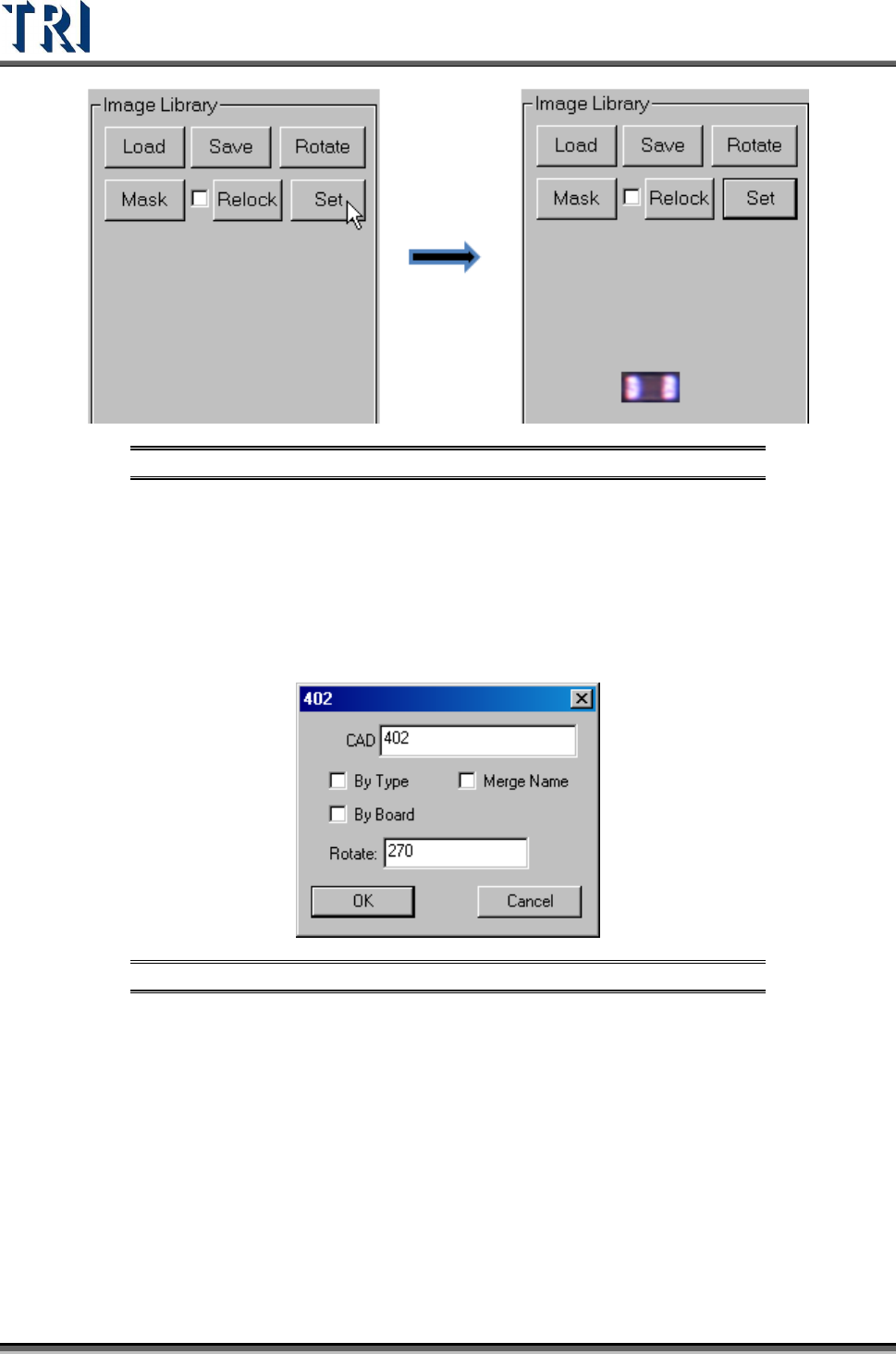
Step1. Move the multi-function box to the alternative image.
Figure 440: Move Multi-Function Box to Alternative Image
Step2. Press [Set] button.
Test Research Inc.
264 TR7500 Series User Guide –Software v.2.9.0
Figure 441: Press Set to Add Alternative Image
Step3. Press [+Alternative] and select the application rules.
Step4. Press [View Model] to review all the alternative images.
11.9.2.5 EditComp
Edit the component type and angle. When the inspection boxes of this component are on
more than one FOV, the [Rotate] Angle cannot be changed here.
Figure 442: Edit Component Type & Angle
[By Type] – apply the type name to the components with same type.
[By Board] – apply the type name or rotate angle to the same components on a
multi-board panel.
[Merge Name ]– The initial character(s) of component combine with original name
to form the new type name.
11.9.2.6 View Model
Review the standard images here or modify the images.