TR7500_Series_Software_v29_En.pdf - 第33页
Test Research Inc. TR7500 Series User Guide – Software v.2.9.0 11 Figure 17: Set Bo ard 1 with CAD Relationsh ip 2.5.2 Get Board Rotati on Angle (Find R1, R2) W he n it is a multi -board panel , user has to find a co mpo…
Test Research Inc.
10 TR7500 Series User Guide –Software v.2.9.0
2.5 Generate Multi-Board CAD Data
The CAD file collected is for a single board, if testing is for a multi-board panel multi-board
data must be created..
If the PCB is a single board, input ‘1’ in column and row field separately and press [Next] to
enter the next step, Fiducial Mark Setting (
2.6).
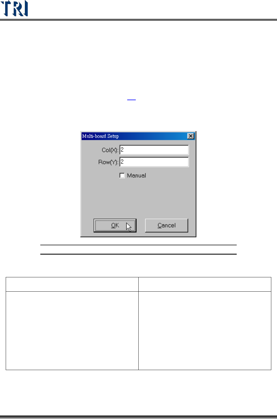
2.5.1 Set Multi-Board Arrangement Data
1. Set Multi-Board matrix (X direction & Y direction board counting).
Figure 16: Multi-Board Setup
Manual-When selected, it means the regular panel; when unselected, it means the special
panel.
Regular Panel Irregular Panel
a. A panel can be mentioned by MxN boards,
Including single board
b. FOV will be arranged in multi-board.
c. Multi-board layout can be changed directly
and don’t have to program again.
a. A panel with different kinds of multi-
boards, it can’t be mentioned by MxN.
b. FOV will be arranged in a single board.
c. If the multi-board layout is changed, user
has to program again.
d. User only has to input the total number of
boards.
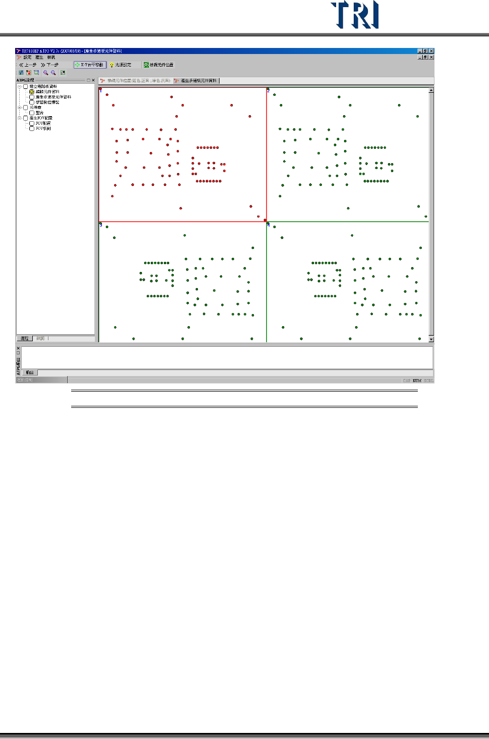
(1) System defines the board at upper-left corner as Board 1. In [Edit Component Data], we
have set the CAD data to cooperate with Board 1, so we only have to set the side and
angle of the other boards except Board 1. Right click on every board to set its side and
angle.
(2) The following is the finished picture.
Test Research Inc.
TR7500 Series User Guide –Software v.2.9.0 11
Figure 17: Set Board 1 with CAD Relationship
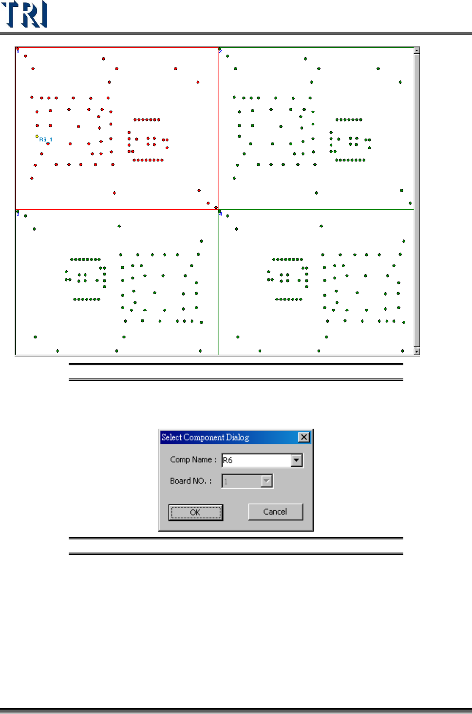
2.5.2 Get Board Rotation Angle (Find R1, R2)
When it is a multi-board panel, user has to find a component in Board 1 and locate it, and
system will specify the same component in the other board for user to locate.
When it is a single board panel or a panel with different sides, the board angle can be
determined from two components on the board. It is better for board angle detection that the
two components have maximum distance from each other.
(1) Double click on the objective component in Board 1.
Test Research Inc.
12 TR7500 Series User Guide –Software v.2.9.0
Figure 18: Set First Component in Board 1
(2) Input the objective component name.
Figure 19: Select a Component Name
(3) Locate the specified component. Move camera to center of the component. Use
[Motion Control] function to move camera to specific direction and distance or click right
button of mouse on image zone to move the camera to the mouse position. Adjust the
size of red frame to suit the specific component. The center can easily be found.