TR7500_Series_Software_v29_En.pdf - 第181页
Test Research Inc. TR7500 Series User Guide – Software v.2.9.0 159 6.6 Lib rary 6.6.1 Verify Figure 265 : Library Verify Tab 6.6.1.1 Component Library Select to enter the [ T une] field. 6.6.1.2 Name Index Select to open…
Test Research Inc.
158 TR7500 Series User Guide –Software v.2.9.0
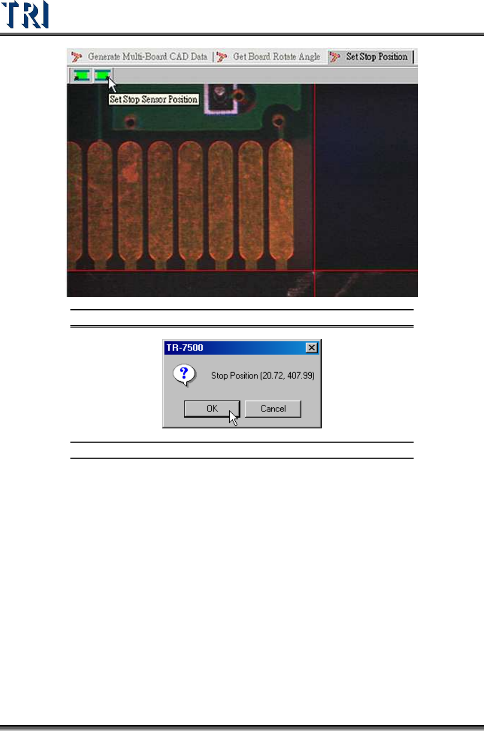
Figure 263: Set Stop Sensor Position
Figure 264: Confirm Stop Position
6.5.5 Board 1 Size
Set board 1 size here.
6.5.6 Mosaic
Press this function to get panel map.
Test Research Inc.
TR7500 Series User Guide –Software v.2.9.0 159
6.6 Library
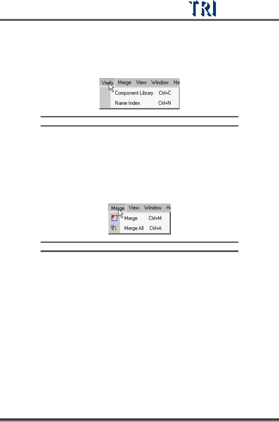
6.6.1 Verify
Figure 265: Library Verify Tab
6.6.1.1 Component Library
Select to enter the [Tune] field.
6.6.1.2 Name Index
Select to open [Name Index] window.
6.6.2 Merge
Figure 266: Library Merge Tab
Merge means for all components on a PCB the system will copy all inspection boxes to every
component depending on the type.
6.6.2.1 Merge
Merge the selected type.
6.6.2.2 Merge All
Merge all types.
Test Research Inc.
160 TR7500 Series User Guide –Software v.2.9.0
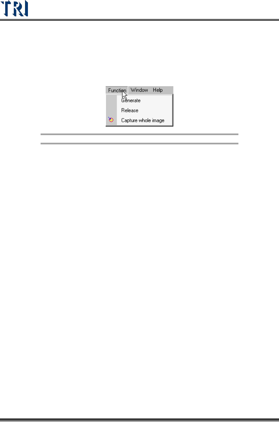
6.7 FOV Generate
Fields of View [FOVs] are used to define inspection areas. One component may have many
FOVs; e.g. one for each pin. Each FOV may have many different inspection functions.
Figure 267: FOV Function Tab
6.7.1 Generate
Press [Generate] then the system will recalculate the deployment of FOVs.
6.7.2 Release
Clear the data calculated previously..
6.7.3 Capture Whole Image
Press to capture FOV images according to the calculation.