TR7500_Series_Software_v29_En.pdf - 第286页
Test Research Inc. 264 TR7500 Series User Guid e –Softwa re v.2.9.0 Figure 441 : Press Set to Add Alt ernative Imag e Step3. Press [+Alternative] and select the application rules. Step4. Press [View Model ] to review all…
Test Research Inc.
TR7500 Series User Guide –Software v.2.9.0 263
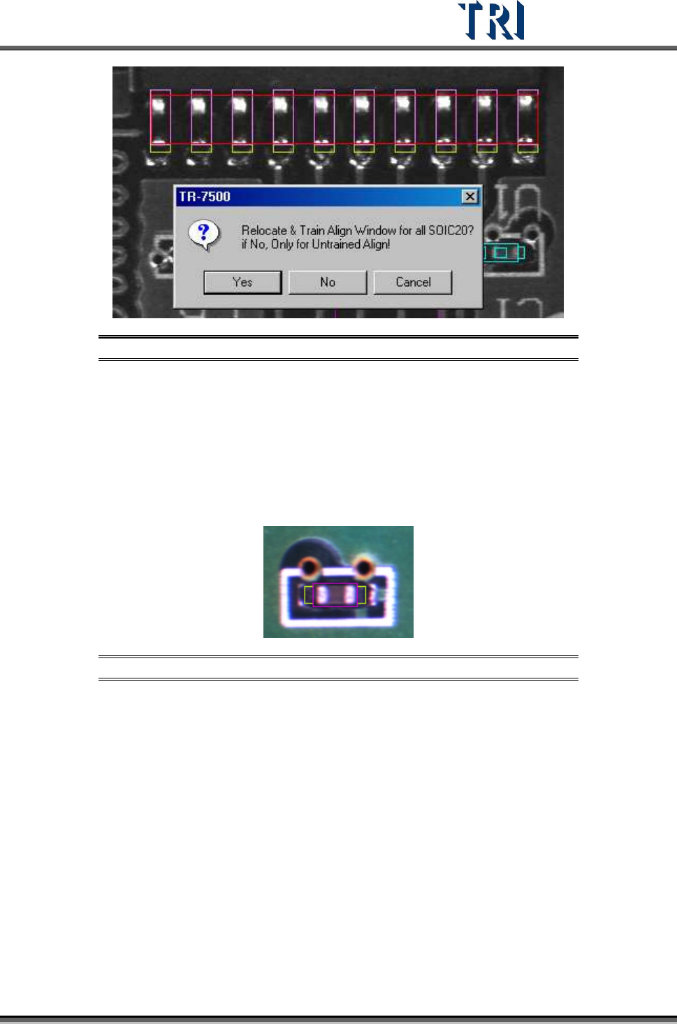
Figure 439: Confirm Relocate & Train Align Window
11.9.2.4 +Alternative
Add an alternative image to [Missing] or [Missing Polarity] window. Adding an alternative
image adds a standard image for the component. The box will be regarded as pass if one or
more images are passed. The number of the alternative images is not limited.
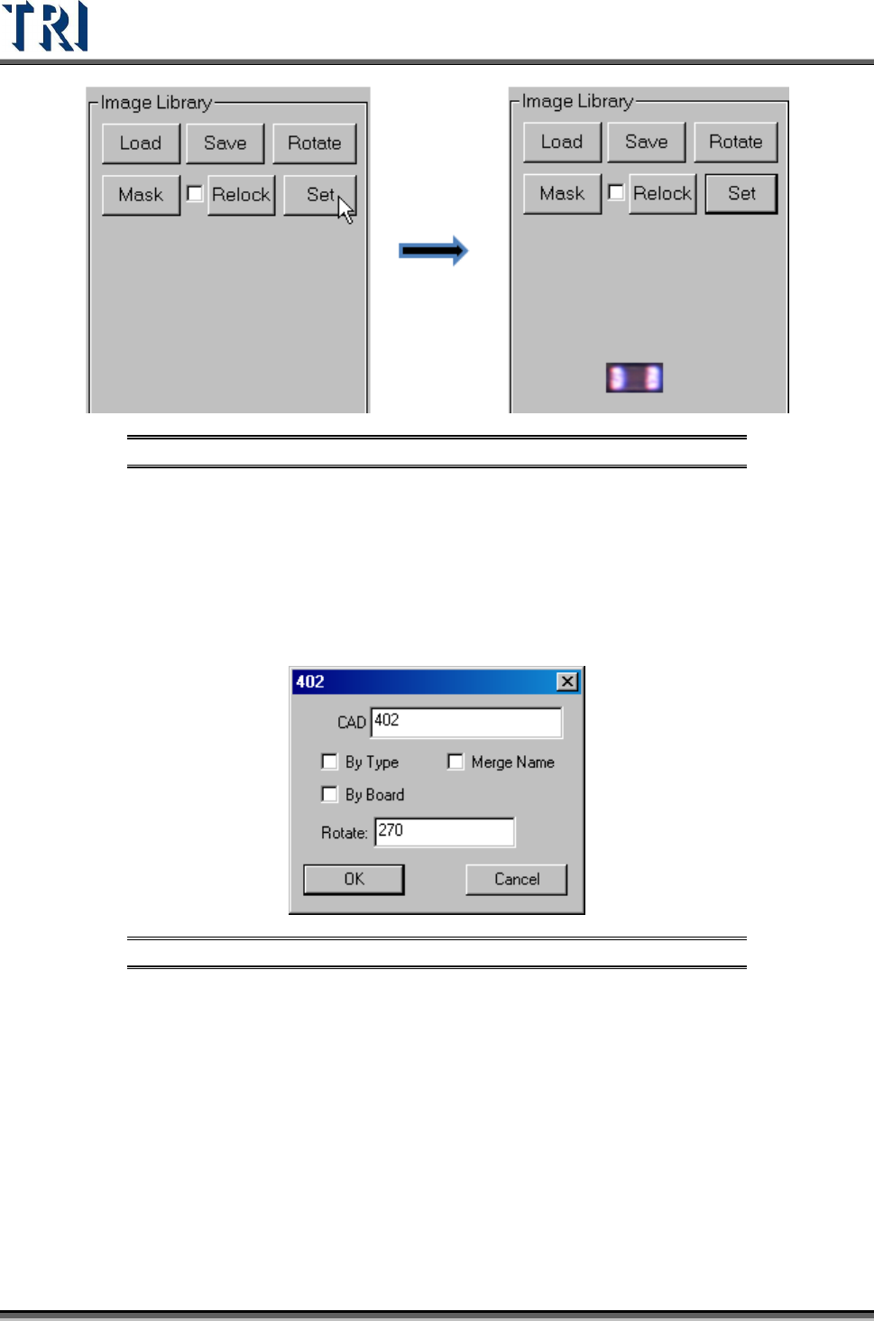
Setting Steps
Step1. Move the multi-function box to the alternative image.
Figure 440: Move Multi-Function Box to Alternative Image
Step2. Press [Set] button.
Test Research Inc.
264 TR7500 Series User Guide –Software v.2.9.0
Figure 441: Press Set to Add Alternative Image
Step3. Press [+Alternative] and select the application rules.
Step4. Press [View Model] to review all the alternative images.
11.9.2.5 EditComp
Edit the component type and angle. When the inspection boxes of this component are on
more than one FOV, the [Rotate] Angle cannot be changed here.
Figure 442: Edit Component Type & Angle
[By Type] – apply the type name to the components with same type.
[By Board] – apply the type name or rotate angle to the same components on a
multi-board panel.
[Merge Name ]– The initial character(s) of component combine with original name
to form the new type name.
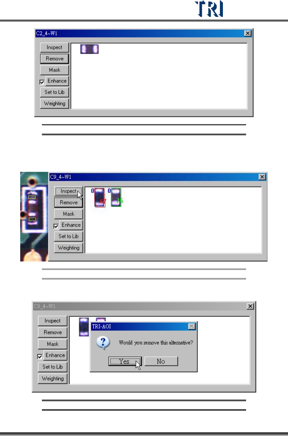
11.9.2.6 View Model
Review the standard images here or modify the images.
Test Research Inc.
TR7500 Series User Guide –Software v.2.9.0 265
Figure 443: View Standard Images
[Inspect] – Review the similarity between the standard image and the image that is
waiting to be measured. The blue figure at the upper left corner represents the
number of times of the enhancement.
Figure 444: Inspect Function with Magnification Shown
[Remove] – Remove the selected image.
Figure 445: Confirm Remove Image