TR7500_Series_Software_v29_En.pdf - 第72页
Test Research Inc. 50 TR7500 Series User Guide – Software v.2.9.0 Figure 91: Uploa d/Download Project Dat a 3.3.4 Panel P arameter 3.3.4.1 Bar Code Tab Figure 92: Panel Paramete r Screen – B ar Code Tab [Setting] – Pre…
Test Research Inc.
TR7500 Series User Guide –Software v.2.9.0 49
3.3.3 Connect Project Server & Project Server Setting
When the project server is installed users may access and control all projects in the AOI
system through the [Project Server] function.
1. Select [Project Server Setting]
2. When the [Project Server] dialog appears, enter the appropriate information in the fields.
3. Click on [Save].
4. Open [Connect Project Server] to enter [Link] mode.
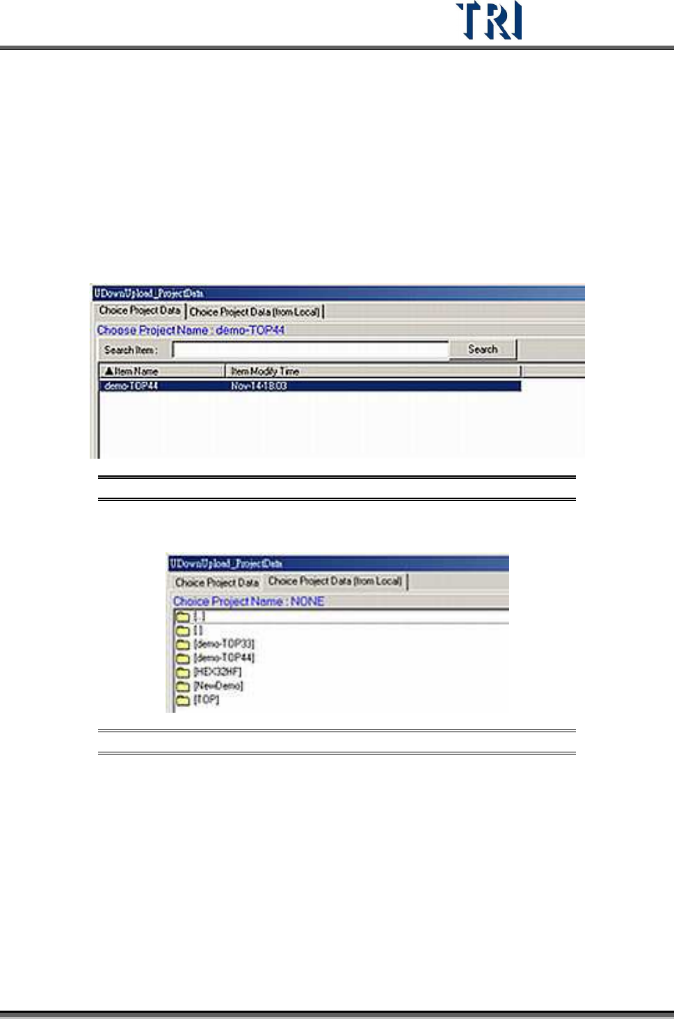
5. The [Project Server] dialog will appear (see figure below). Select the project to download.
Figure 89: Project Server Dialog
6. User may download the local project by selecting [Choose Project Data(from Local)]
Figure 90: Project Server Dialog – Choose Project from Local
7. After saving each program, the system will automatically save and upload the project
back to the [Project Server] under [Link] mode.
Test Research Inc.
50 TR7500 Series User Guide –Software v.2.9.0
Figure 91: Upload/Download Project Data
3.3.4 Panel Parameter
3.3.4.1 Bar Code Tab
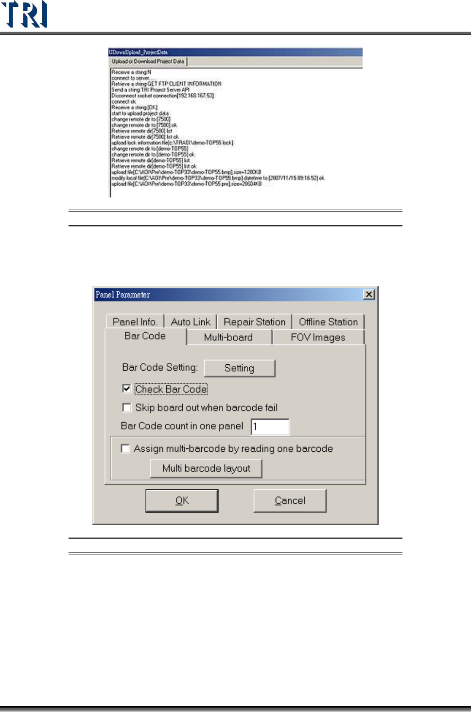
Figure 92: Panel Parameter Screen – Bar Code Tab
[Setting] – Press this button is to enter the Barcode Setting Dialog.
[Check Barcode] –Check to start the function of reading barcode. It must read
barcode before inspecting.
[Barcode count in one panel] – Input the number of barcodes to read on the whole
panel.
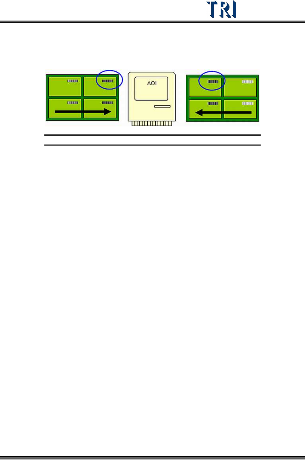
[Assign multi-barcode by reading one barcode] – When there is a regular
arrangement of the barcode, this function can be used to read only one barcode
and the system can calculate the others. If the PCB is sent to the machine from the
Test Research Inc.
TR7500 Series User Guide –Software v.2.9.0 51
left, read the barcode on the board that is at the upper right corner. If the PCB is
sent to the machine from the right side, read the barcode on the board that is at the
upper left corner. When this item is checked, remember to set the arrangement in
[Multi Barcode Layout].
Figure 93: Panel Input Direction from Left or Right
[Multi Barcode Layout] – Only when the value in [Barcode count in one panel] is
greater than 1, this button becomes active and allows users to enter the [Barcode
Layout Dialog] as shown in the following figure.
[Panel input direction] – Set the input direction [From left side] or [From right side]
[Decimal/Hex]. – Set the barcode type.
[Barcode layout] – Set the corresponding layout of the multi-board.