TR7500_Series_Software_v29_En.pdf - 第312页
Test Research Inc. 290 TR7500 Series User Guid e –Softwa re v.2.9.0 12 I NSPE CTION D IALO G F UNCTIO N 12.1 Image Diag ram Functions Figure 481 : Image Diagra m Functions [Alternativ e ] – Add an alternativ e t o a co…
Test Research Inc.
TR7500 Series User Guide –Software v.2.9.0 289
11.9.14 Change FOV
11.9.14.1 Previous
Review the previous FOV.
11.9.14.2 Next
Review the next FOV.
11.9.14.3 OK
Close the [Train] dialog.
11.9.15 Information Bar
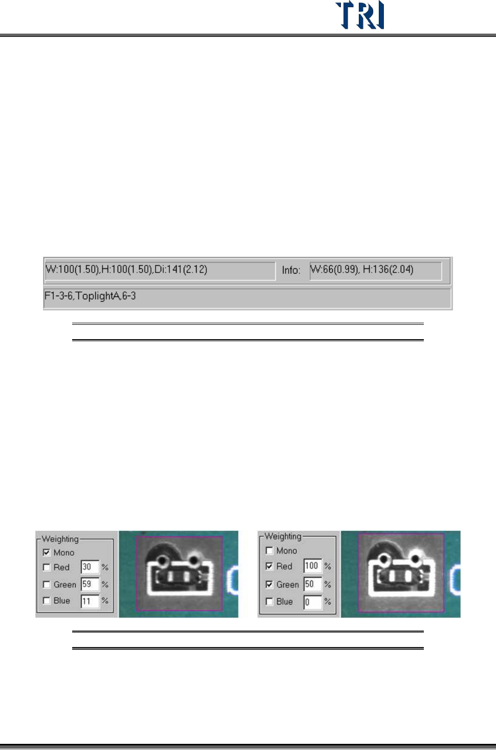
Figure 479: Information Bar
Referring to the figure above, [W] is the horizontal width of the control box. The first number
(100) is pixels, and the second (1.50) is the unit of the measurement in millimeters. [H] is the
vertical height of the control box and [Di] is the diagonal length.
The [Info] section displays the width and height of the inspection box.
The field at the bottom displays first, the [FOV Image Label] number (F1-3-6). [Toplight A] is
the lighting method of the FOV. The last numbers (6-3) refers to board 6 image 3.
11.9.16 Weighting
After checking [Mono] or [RGB], the image in the multi-function window displays according to
the setting. This is for user's reference.
Figure 480: Examples of Weighting: Mono (left) & RGB
Test Research Inc.
290 TR7500 Series User Guide –Software v.2.9.0
12 I
NSPECTION
D
IALOG
F
UNCTION
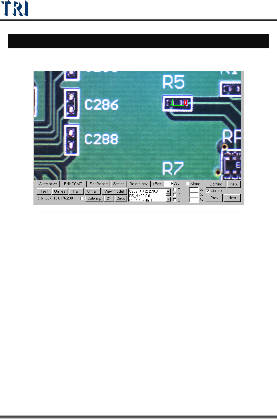
12.1 Image Diagram Functions
Figure 481: Image Diagram Functions
[Alternative ]– Add an alternative to a component.
[Edit COMP]. – Edit component name and angle.
[SetRange] – Set search range for an inspection box.
[Setting] – Set the pass level.
[Delete box] – Delete selected box.
[+Box] – Add one box to selected component.
[Test/UnTest] – Set selected box as test or untest.
[Train/UnTrain] – Train inspection or set trained box as untrained.
[View model] – Review the standard images
[Setwarp/Delwarp] – Set or delete [Warp].
[2X] – Show the double-sized FOV image. The display area is the multi-function
location and the image is reviewed for test.
[Save] – Save the image to the folder.
[Lighting] – Change the lighting for inspection.
[Insp.] – Inspect the current FOV.
[Visible] – Selecting this displays the inspection boxes.
Test Research Inc.
TR7500 Series User Guide –Software v.2.9.0 291
[Mono/R/G/B] – Let the image in the multi-function window display according to the
setting.
[Prev/Next] – Go to the next or previous failed FOV.
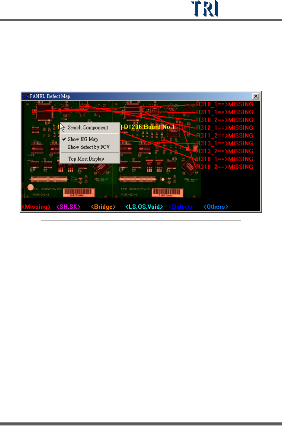
12.2 Panel Defect Map
Right click on the map, then the following pop-up menu will display.
Figure 482: Panel Defect Map
[Search Component] – Select this button, then specify a component to be marked
on the map.
[Show NG Map] – Checking this item displays the panel defect map after the next
inspection; otherwise, the map will not display after the next inspection.
[Show defect by FOV] – The system will display all defects on the panel when this
item is not selected. When selected, the system will only display the defects that
are reviewed in the [Results] dialog.
[Top Most Display] – When the item is selected, this [Panel Defect Map] will be
displayed at the top from the next inspecting.