TR7500_Series_Software_v29_En.pdf - 第128页
Test Research Inc. 106 TR7500 Series User Guid e –Softwa re v.2.9.0 3.10.16 Inline Compone n t Data Output to SPC Output the [Cpk Data Co llection] to SPC system. The output path is the same as the pa th specified in [P …
Test Research Inc.
TR7500 Series User Guide –Software v.2.9.0 105
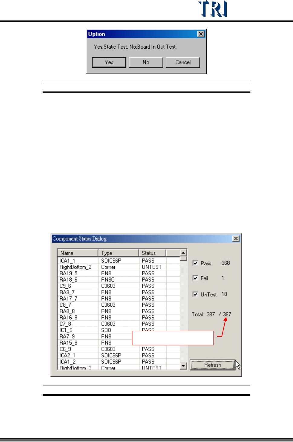
Figure 172: Confirm Static or Board In/Out Test
3.10.12 Resend Image Data for Repair
This function is enabled when [Parameter/User Mode/Link to Repair Station] is selected.
Press the item and the system will send the data to repair station (Including *dir.1, *.win,
*.img, *.bmp).
3.10.13 Enable Inspection Data Collection
Select this item to save the result for all components as a text file. The file will be saved in
the folder that the project is saved in and the file name is “Year-Month-Date-Time”.
3.10.14 Component Status
This can only be selected in the [Train] dialog.
After selecting [Pass], [Fail] and [Untest], press [Refresh]. The system will display the number
of components which are passed, failed or untest.
Number of components
Figure 173: Component Status Dialog
3.10.15 Generate Real Image Data
Generate the image to ICT or ATE machine.
Test Research Inc.
106 TR7500 Series User Guide –Software v.2.9.0
3.10.16 Inline Component Data Output to SPC
Output the [Cpk Data Collection] to SPC system. The output path is the same as the path
specified in [P
ARAMETER
>
P
ANEL
>
R
EPAIR
S
TATION
]..
After loading a .PRE file, save the .PRE file again to output the specification file. The name of
the file is the model name and its file name extension is .LSU. A .PRE file only has to be
saved once after the project is finished. If there is a new project created or a project is
modified, the system will send the LSU file automatically.
After inspecting a panel, the system sends a PFL file to the specified drive..
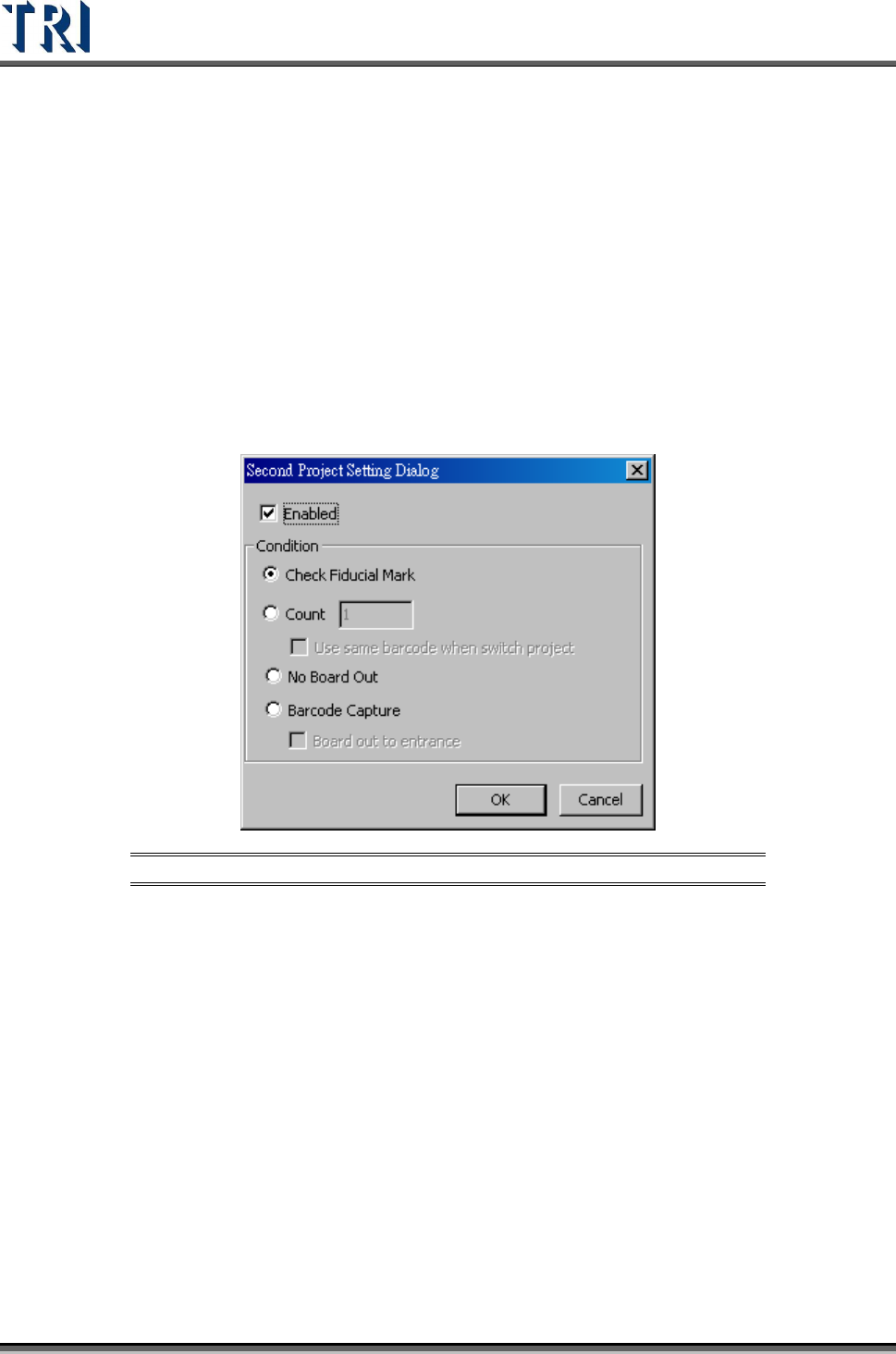
3.10.17 Second Project
Select two projects to be open in turn automatically.
Figure 174: Second Project Data Setting Dialog
[Enabled] – Check to start the function. Load two projects at the same time and the
system will change the project to inspect according to the conditions.
[Check Fiducial Mark] – When the system can’t find a fiducial mark it will change to
use the second project.
[Count] – Select and input number. After the first project is inspected for the
specified number of times, it will change to use second project. When set to “1”, the
barcode will remain the same for the second program.
[No Board Out] – After a board is sent into the machine, it will be inspected by the
first then the second project in sequence, then the board is sent to exit.
[Barcode Capture] – Change programs according to the type of barcode (software
or hardware barcode). If both fail, the board will be sent back to the start position.
If this function is selected, the two programs must have different barcode
types: one hardware and one software.
Test Research Inc.
TR7500 Series User Guide –Software v.2.9.0 107
If the two programs have the same type of barcode, the system will not
inspect and require two new programs be loaded.
The system initially checks the hardware barcode for the first program.
The system must be set to [Inline] mode.
[Board Out to Entrance] – selecting this will send the board back to the entrance if
barcode checking fails.
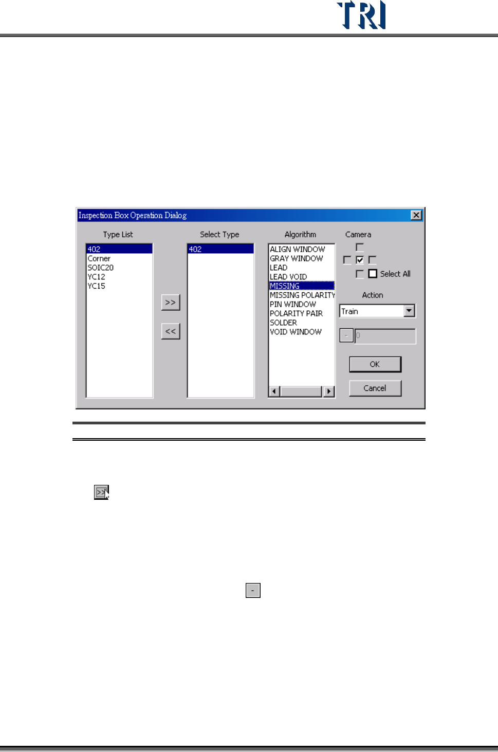
3.10.18 Inspection Box Operation
Change the parameters for a specific inspection window of a specific component type.
Figure 175: Inspection Box Operation Dialog
[Type List] – System shows all the types in the project.
[Select Type] – Select a type to change. Select a type in [Type List] field first then
press
to move the type to [Select Type] field.
[Algorithm] – Select the inspection window types that you want to modify here.
Camera – Select the camera that you want to modify.
[Camera] – Select the camera.
[Action] – Select one action.
(1) [Change Passlevel] – Change pass level. When selecting this item, the toolbar
below will be enabled. Click on the
button to switch plus or minus sign. Plus
sign means to add the number that you input back and the minus sign means to
reduce the number that you input back. For example, the original score is 60. If
the setting is +5, the score will be changed to 65. If the number input is 0, the
parameter will be changed to the original score. The corresponding parameters
are the following:
Missing, Missing_Polarity, Lead – Score
Void, Lead Void – Bright Ratio
Solder – Bridge Ratio
(2) [Delete] – Delete the selected inspection box