TR7500_Series_Software_v29_En.pdf - 第202页
Test Research Inc. 180 TR7500 Series User Guid e –Softwa re v.2.9.0 8.3 View Command Figure 301 : View Comman d Menu Show di rectionality of the pins w ith small circle. The correct direction is show n as t he following.…
Test Research Inc.
TR7500 Series User Guide –Software v.2.9.0 179
8.2.6 Rotate Side
Rotate the pin direction 90 degrees counterclockwise by clicking once.
Figure 299: Rotate Pin Direction Command Result
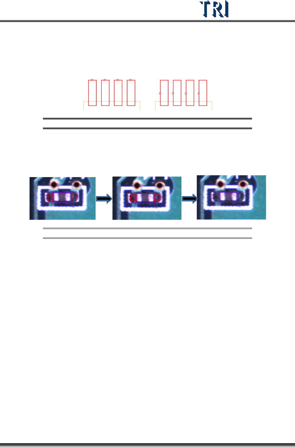
8.2.7 Change Shape
The function is to change the window shape from square to circle or from circle to square. It
only works for [Void] or [Solder] window.
Figure 300: Change Window Shape Command Result
Test Research Inc.
180 TR7500 Series User Guide –Software v.2.9.0
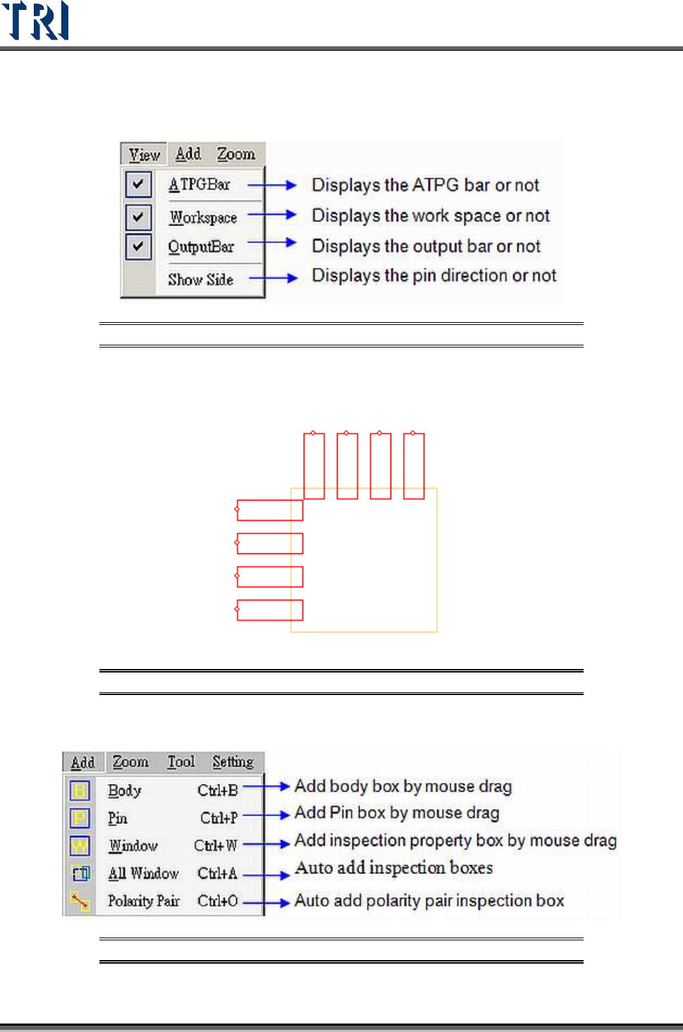
8.3 View Command
Figure 301: View Command Menu
Show directionality of the pins with small circle. The correct direction is shown as the
following. If the direction is wrong, to select [Edit/Rotate Side] to change the direction.
Figure 302: Example of Show Side Function
8.4 Add Command
Figure 303: View Command Menu
Test Research Inc.
TR7500 Series User Guide –Software v.2.9.0 181
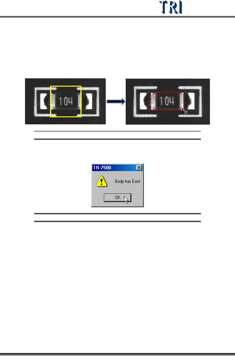
8.4.1 Body
The system will get the size and position of components by using the Body box. Creating a
Body box also can help for editing the library.
Press [Add > Body] and the system will create a square, yellow Body Box. Adjust the size of
the Body Box by clicking and dragging the mouse. Move the position of the box to the
component center by [Motion Control] dialog.
Figure 304: Adding a Body Box
Only one Body window is allowed for each component. If the Body already exists and you
also press [Body] the following window will appear. Press [OK].
Figure 305: Existing Body Box Warning Message
8.4.2 Pin
Use of the Pin Box lets the system get the size, position and number of IC pins. Creating a
Pin Box also can help for editing the library.
Press [Add > Pin], then click and drag the mouse to create a Pin Box. The initial position of
clicking must be at the same side with IC pin against body window because the system
judges the position of IC pins by initial clicking. If a pin is created at one side of the body then
moved to another side, the system will make mistakes later.
Adjust the size and position to match the IC lead.