TR7500_Series_Software_v29_En.pdf - 第326页
Test Research Inc. 304 TR7500 Series User Guid e –Softwa re v.2.9.0 6. Press [Confirm PASS] or [Con f irm FAIL] then thi s data is canceled and t he nex t result appears. 7. W hen the settings are ch ang ed at the Of fli…
Test Research Inc.
TR7500 Series User Guide –Software v.2.9.0 303
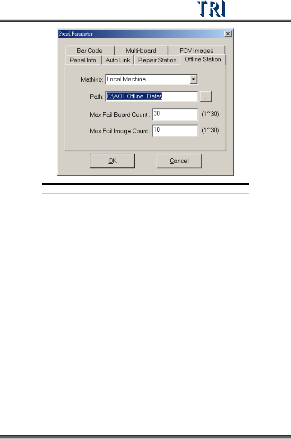
Figure 498: Offline Station Dialog
The [Machine] option will have a list of AOI machines. Users may link to any machine by
using the drop-down menu. If the connection cannot be completed, check and complete the
connection between AOI and Offline Editor in order to select another AOI machine.
15.4.2.3 TR7500 Machine
1. Refer to the figure above. Select [P
ARAMETER
>
U
SER
M
ODE
>
L
INK
T
O
O
FFLINE
S
TATION
]
2. Select [P
ARAMETER
>
P
ANEL
>
O
FFLINE
S
TATION
] and set the path link to the specified
folder. This path must link to the folder that is the same as what the offline editor is set to.
3. Input [Max Fail Board Count] and [Max Fail Image Count].
15.4.3 Operation Instructions
15.4.3.1 Result Dialog
1. Copy the testing project file and the [FOV Image] folder to the Offline Editor.
2. When the TR7500 has tested one time, the failed images and [*.pnl] file are transferred to
the [AOI_Offline_Data] folder of the Offline Editor.
3. Open the main program and load the [*.pre] file that is the same as the inspection project
on the TR7500 main machine.
4. The software will create an authorized flag called [AOI ID.run] to set a flag to the other
TR7500 machines in order to avoid jammed communication. The authorized flag will
control the connection traffic of all systems and save unsent data back to the original
machines for the next available connection to [Offline Editor].
5. Press [I
NSPECTION
>
I
NSPECT
FOV
I
MAGES
] then the system starts to inspect the saved
FOV images. If the TR7500 has sent a failed image, the system uses these failed images
in place of the saved images and inspects them. Set the search range, pass level or add
alternative images according to the inspection result.
Test Research Inc.
304 TR7500 Series User Guide –Software v.2.9.0
6. Press [Confirm PASS] or [Confirm FAIL] then this data is canceled and the next result
appears.
7. When the settings are changed at the Offline Editor, the system saves a [*.fbk] file in the
[AOI_Offline_Data] folder. When AOI is transferring data to the Offline Editor, it reviews
the [*.fbk] file at the same time and the inspection parameters are modified at the next
inspection.
15.4.3.2 Train Dialog
1. Press [Train] to enter the [Train] dialog.
2. Click on an inspection box to review the result.
3. Right click on the inspection box and select [V
IEW
>
S
HOW
D
ATA
C
OLLECTION
C
HART OF
THIS
B
OX
]. The system shows the latest 1000 data of this box.
4. Change the search range, pass level or add an alternative image in this window.
Test Research Inc.
TR7500 Series User Guide –Software v.2.9.0 305
A
PPENDIX
1
L
IGHTING
C
OMPENSATION
1. Lighting Compensation
This function uses software to perform lighting compensation for every camera. The standard
is that when the lighting range is established as 60mA and the intensity is 128 at all adjusted
zones, the gray level of the gray card image is compensated to 100.
1. Press [S
TART
>
R
UN
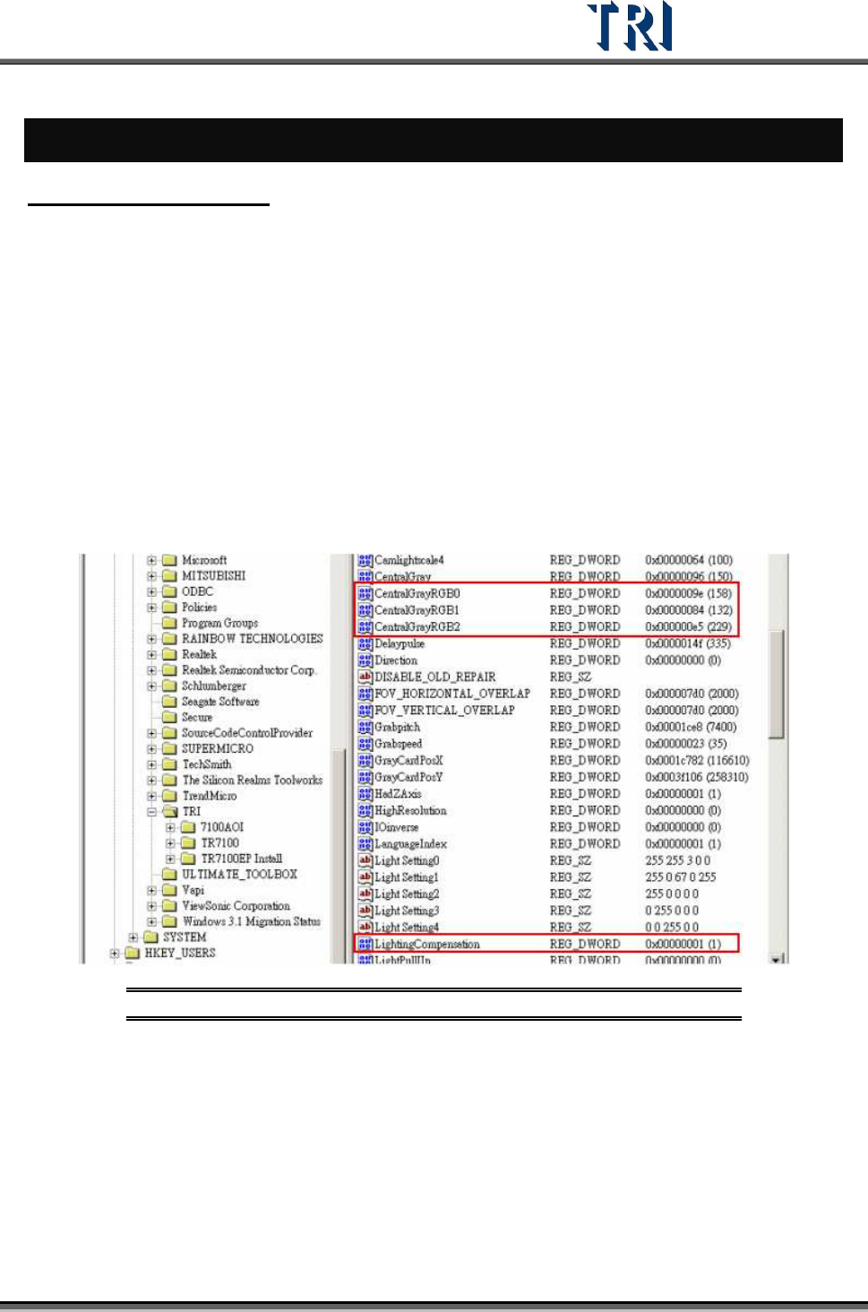
]. Key in “regedit” to open the registry. Enter
“HKEY_LOCAL_MACHINE\HKEY_LOCAL_MACHINE\SOFTWARE\TRI\” and check if
there is a DWORD variable named “LightingCompensation”. If the variable does not exist,
open the main program of TR7500 and the variable is created automatically.
2. To execute lighting compensation, change the value of the variable to “1”.
3. The first time the lighting is executed, the system creates the following four parameters:
[Central/Gray] – the objective gray level for the four side-view cameras -- and
[CentralGrayRGB0], [CentralGrayRGB1], and [CentralGrayRGB2] -- the objective gray
level for R, G, B sensors.
Figure 499: Lighting Compensation Parameters
4. Open the TR7500 main program of and enter [U
TILITIES
>
C
AMERA
A
LIGNMENT
].