TR7500_Series_Software_v29_En.pdf - 第230页
Test Research Inc. 208 TR7500 Series User Guid e –Softwa re v.2.9.0 [Ca mera] – Select Top or Angle Camera v ie w. [Li ghting] – Select Ligh t type. [M ethod] – Select the ins pection windows for property chan g e.…
Test Research Inc.
TR7500 Series User Guide –Software v.2.9.0 207
8.7.3 Property
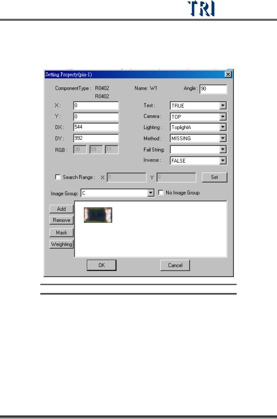
Set the properties of the inspection box.
Figure 350: Set Inspection Box Properties Dialog
[(pin-1)] – Displays the serial number of the IC pin that the selected inspection
box inspects. When showing (pin-1), it means that the selected box doesn’t
inspect any IC pin.
[Component Type] – Displays the component type
[Name] – Displays the inspection box name
[Angle] – Displays the rotation angle of the component.
[X] – Component on the X coordinate position.
[Y] – Component on the Y coordinate position.
[DX] – The component X coordinate on the center.
[DY] –The component Y coordinate on the center.
[Test] – Select TRUE to enable inspection, FALSE to disable inspection.
Test Research Inc.
208 TR7500 Series User Guide –Software v.2.9.0
[Camera] – Select Top or Angle Camera view.
[Lighting] – Select Light type.
[Method] – Select the inspection windows for property change.
[Fail String] – Users can separate the same method into different fail strings
under [Library]. Each [Void] under the same component may have different [Fail
String] and will be labeled and sent to [Repair Station] as the changed one. Also,
changing the variables under the same algorithm will not affect the different [Fail
String]. The [Fail String] will remain default if the user decides not to change it.
[Inverse] – Turn on [Inverse] by selecting [True]. This will invert all the inspection
results. The inspection result of [Pass] will become to [Fail], and [Fail] to [Pass]
[Search Range] – Select this item to set the search range for [Missing] or [Lead]
box manually. After it is set, the latter X and Y fields display the range (unit: um).
The X and Y fields are just for review and cannot be filled. If the range is not set,
the X and Y field display “0” and the system sets the range automatically.
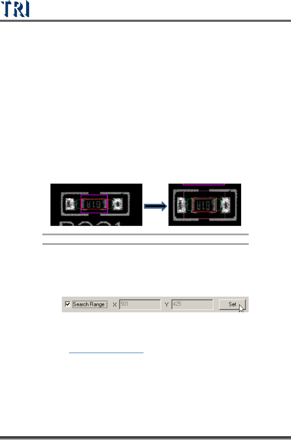
Step1. Open [Property] dialog and check [Search Range]. A thick line and purple
frame appear on the painted area.
Figure 351: Select & Display [Search Range]
Step2. Click on the box to set and then adjust the purple frame to suit the search
range. The search range cannot be smaller than the inspection box.
Step3. Press [Set] then the setting is finished. The X and Y field display the length
and width of the search range.
Step4. The search range is displayed by a thin line and purple frame.
[Image Group] – When the components have the same type but are in different
groups, the image must be set for different groups. See more about groups in
Chapter
5 Edit Component Data
[No Image Group] – After choosing this, users may select [Group] which
contains only those without image taken. For example, if there are two groups of
C and R under Type 0402, and C already has an image taken, but R does not.
The user may only see R under [Group] if the [No Image Group] is selected.
[ADD] – Add image to component image library from missing or lead inspection
windows.
[Remove] – Remove the select image to component image library.
Test Research Inc.
TR7500 Series User Guide –Software v.2.9.0 209
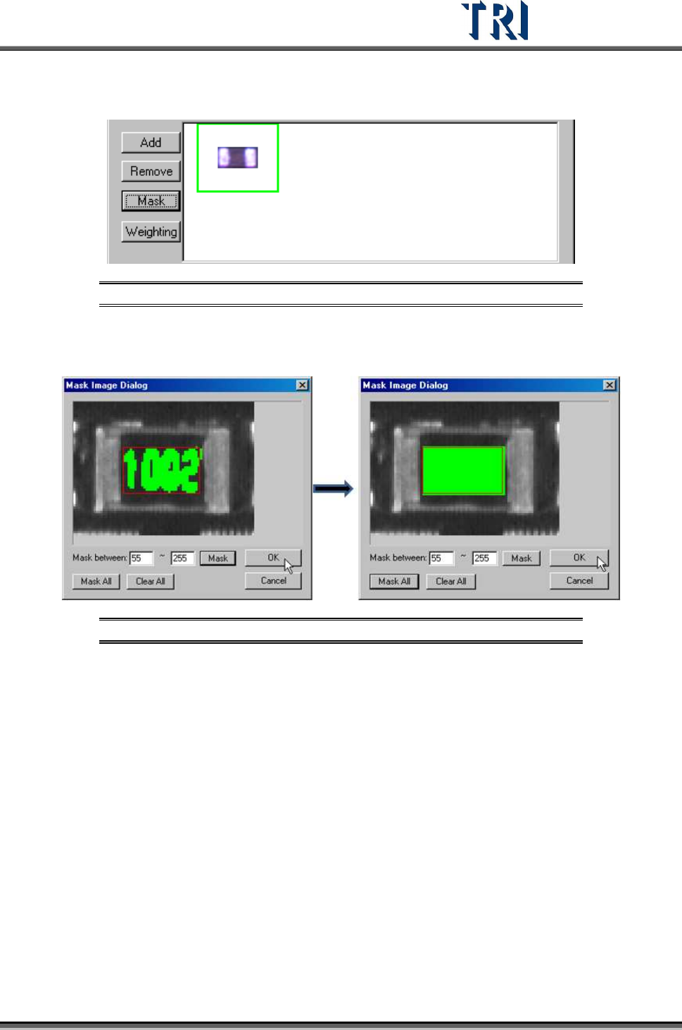
[Mask] – Masks the component image with a non-inspection area or non-regular
area for pattern search. A green frame appears if a mask is set for the image.
Figure 352: Image with Mask Set
[Mask between] – Sets mark range gray level between 0~255 depending on
the character. The mask mode has good tolerance for pattern searching.
Figure 353: [Mask Between] (left) & [Mask All]
[Mask All] – Mask all area in the red window.
[Clear All] – Clear all mask settings.
[Weighting] – Set the weighting for the image that is selected. The setting will be
used for all standard images of this type.