TR7500_Series_Software_v29_En.pdf - 第189页
Test Research Inc. TR7500 Series User Guide – Software v.2.9.0 167 7.2 Se t Specif ic Lighting There are 13 kinds o f lighting sour ces that wi ll be used while doing a pro ject. The 13 kinds o f lighting are also show n…
Test Research Inc.
166 TR7500 Series User Guide –Software v.2.9.0
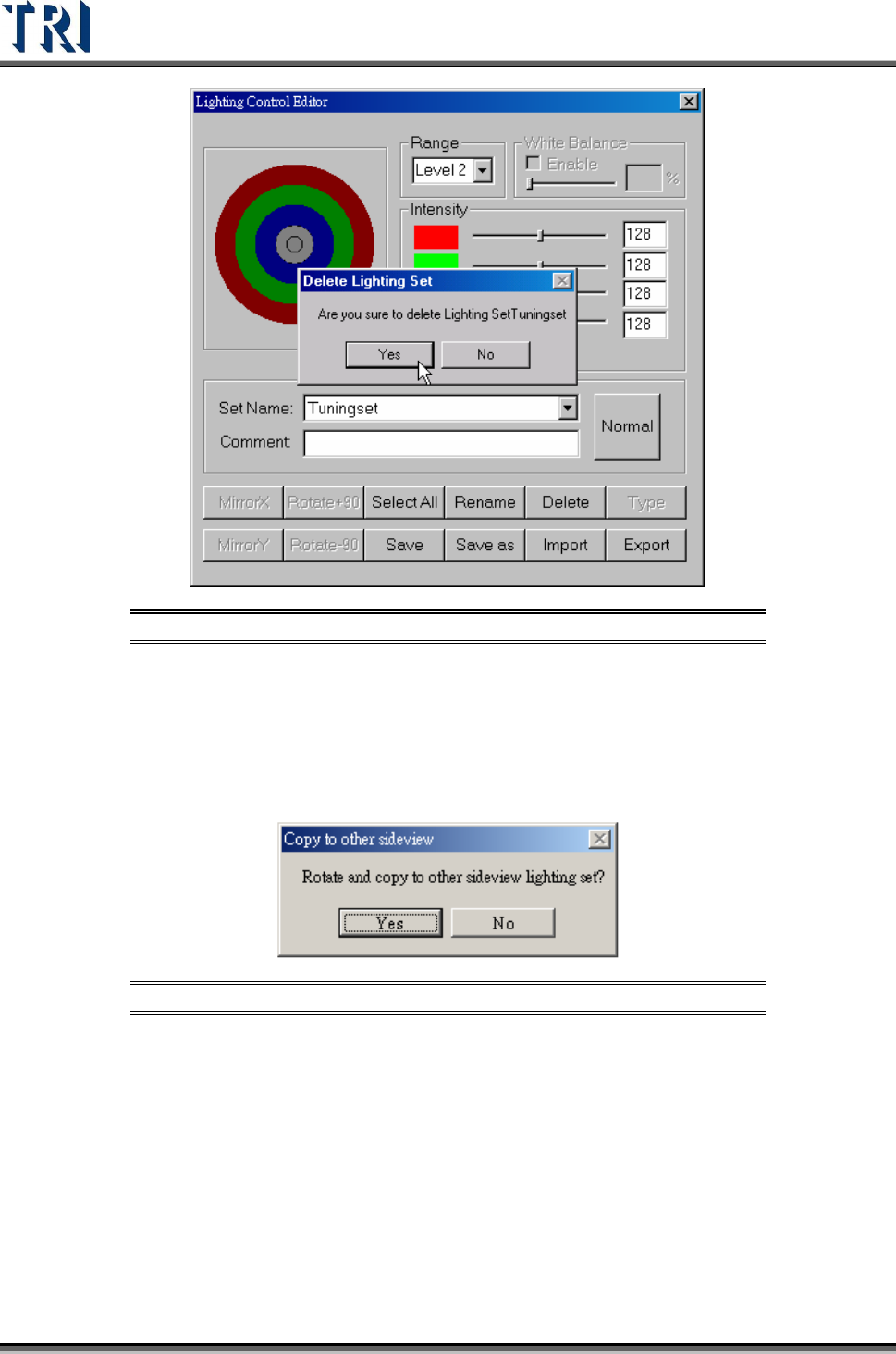
Figure 275: Delete Lighting Set Dialog
(14). [Type] – When [Set Name] is set to “All”, this function will show all default
lighting.
(15). [Save] – Save current light setting parameter. When the lighting that is
modified is [AnglelightA] or [AnglelightB], the system asks to confirm applying the
setting to corresponding lightings.
Figure 276: Confirm Copy Sideview Lighting
(16). [Save as] – Save current light setting under a new name.
(17). [Import] – Input LED lighting definition file from outside. The file name
extension is [*.LED].
(18). [Export] – Output LED lighting definition to file.
When opening a new project, the system sets [C:\AOI\DEFAULTLED7500.LED]
file as the default for the new project.
Every change for lighting in the project is saved in the current project. If you want
to share the lighting to another project, you have to [Export] the current lighting
then [Import] them when opening the other projects.
Test Research Inc.
TR7500 Series User Guide –Software v.2.9.0 167
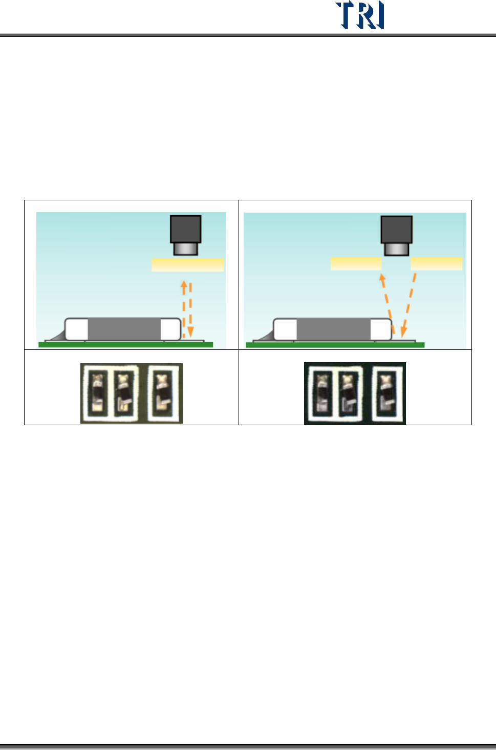
7.2 Set Specific Lighting
There are 13 kinds of lighting sources that will be used while doing a project. The 13 kinds of
lighting are also shown when the [Normal] button is pressed. These 13 types are: two fiducial
lighting types [Fiducial0/1], one lighting [Maplight] for capturing the panel map, two top
camera default lighting types [ToplightA/B], two front camera lighting types [FrontlightA/B],
two rear camera types [RearlightA/B], and two each for left and right cameras [LeftlightA/B]
and [RightlightA/B].
The setting of the lighting looks at the states, such as board color of the circuit, solder joints,
and so on.
Test Research Inc.
168 TR7500 Series User Guide –Software v.2.9.0
8 E
DIT
C
OMPONENT
L
IBRARY
C
OMMANDS
The main screen used for editing the component library Is shown below. All commands and
icons are explained in this chapter.
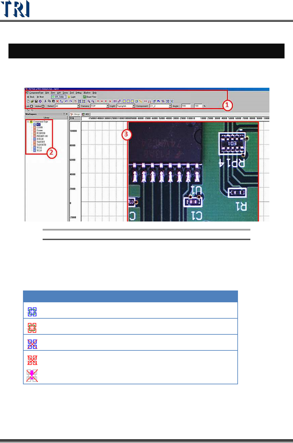
Figure 277: ATPG Component Main Screen
(1). Toolbar – All tools/commands needed to create a library. The tools are explained
below in this chapter.
(2). Type List – Lists all types of components on this PCB. The icons mean the
following.
ICON DESCRIPTION
The type has at least one inspection box and has been saved.
The type has no inspection box and has been saved.
The type has at least one inspection box and has not been saved.
The type has no inspection box and has not been saved.
This icon will appear if an image is not added under [Missing] or
[Lead] boxes. The boxes will be displayed in orange, not purple.
(3). Image Zone – Arrange inspection boxes and create library here. Use the mouse
(clicking and dragging) to select boxes.