TR7500_Series_Software_v29_En.pdf - 第107页
Test Research Inc. TR7500 Series User Guide – Software v.2.9.0 85 3.5 Procedu re: Create a Ne w CAD File Click on [CAD File/New ] t o create a new file. Figure 142 : Select New CAD File Move the camera and use the select…

Test Research Inc.
84 TR7500 Series User Guide –Software v.2.9.0
3.4.12 AOI Check
Load the .AOI file that includes at least the five mandatory fields, then the system will
compare the component information in the .PRE file with the data in the .AOI file. System will
add the components that are only listed in the .AOI file.
The new components have to be merged using the [Train] dialog first then capture the FOV
images again to do fine tuning.
Test Research Inc.
TR7500 Series User Guide –Software v.2.9.0 85
3.5 Procedure: Create a New CAD File
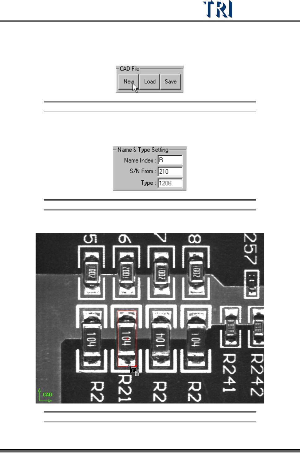
Click on [CAD File/New] to create a new file.
Figure 142: Select New CAD File
Move the camera and use the selection tool then press to set the origin.
Input data at [Name&Type Setting] field
Figure 143: Name & Type Setting Dialog
Move selection tools to the component center.
Figure 144: Use the Selection Tool
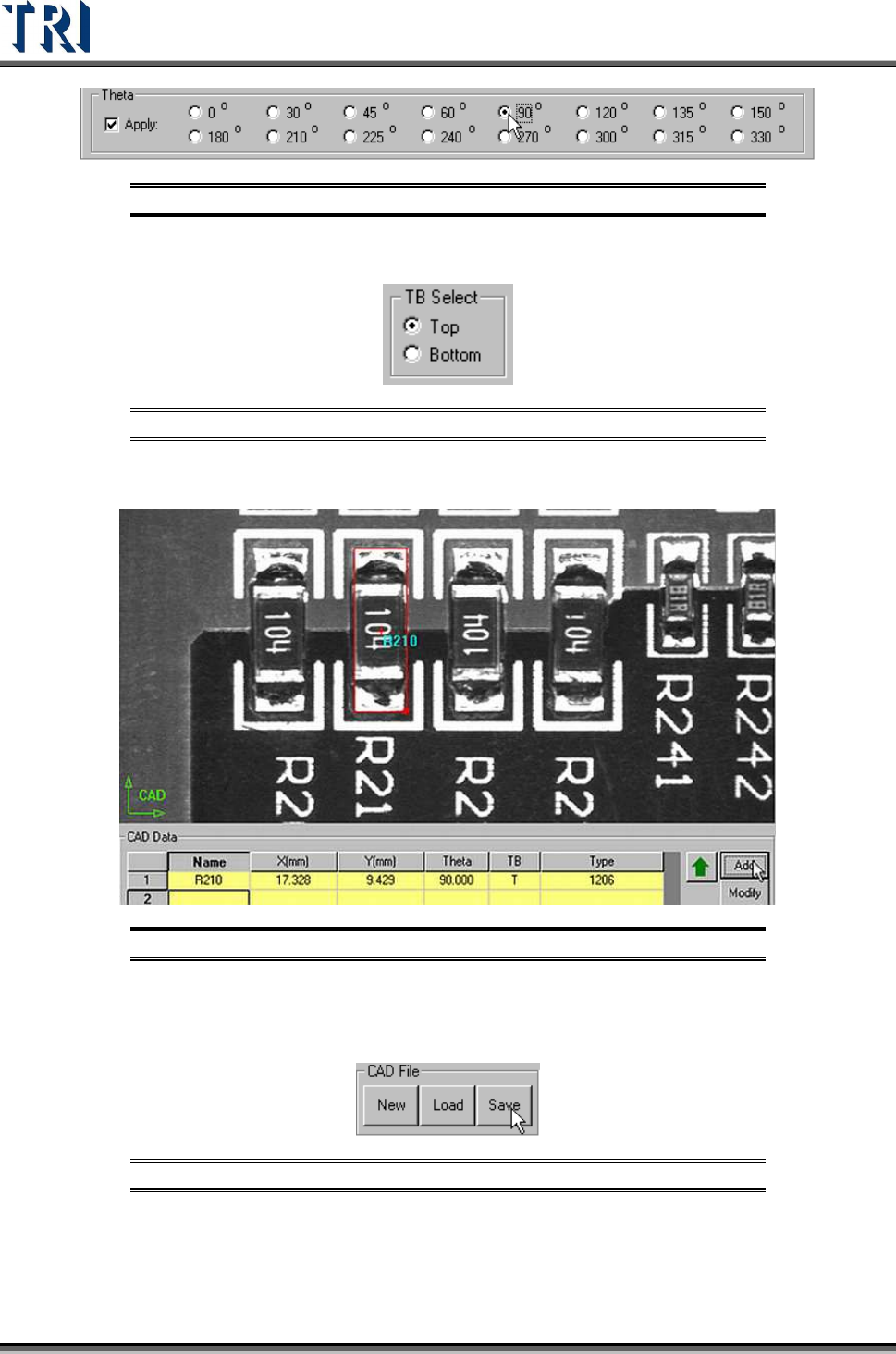
Check [Apply] and select an angle.
Test Research Inc.
86 TR7500 Series User Guide –Software v.2.9.0
Figure 145: Select a Theta Angle
Select [T/B Side]
Figure 146: Select Top/Bottom
Press [CAD Data/Add] to create the component data.
Figure 147: Click “Add” to Add Component Data
Follow the above steps to add other components.
Press [CAD File/Save] to save AOI file.
Figure 148: Select Save CAD File