TR7500_Series_Software_v29_En.pdf - 第273页
Test Research Inc. TR7500 Series User Guide – Software v.2.9.0 251 Figure 419 : Data Collection Chart 2 –Chang e Pass Leve l 11.6.2 Copy Copy the size or position t o the other compone nts w ith same type. Figure 420 : C…
Test Research Inc.
250 TR7500 Series User Guide –Software v.2.9.0
Figure 417: Show Pin Direction
[Show Box’s Weighting Image in Control Box] – This allows the control box to have
the same weighting as the selected inspection box. Only in TR7500 series.
[Show Panel Defect Map] – A defect map will appear in the top-left corner after
each inspection.
[White Balance] – FOV will show with white balance enhancement. Only in TR7500
series.
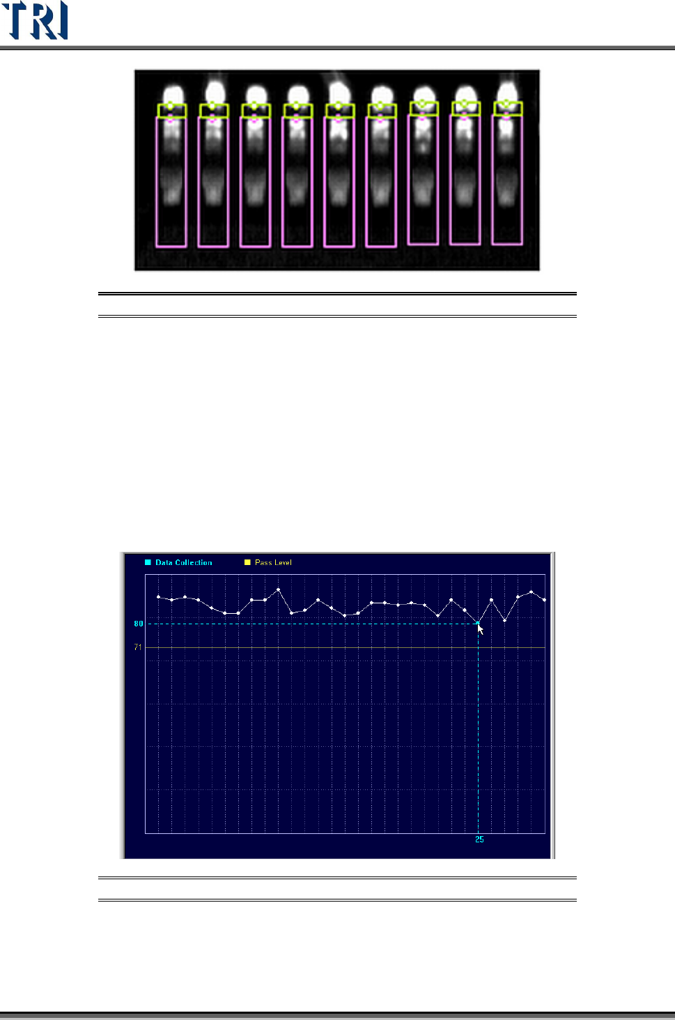
[Show Data Collection Chart of this Box] is enabled only when [P
ROGRAM
>
A
UTO
P
ASS
L
EVEL
S
ETTING
>
I
NLINE
D
ATA
C
OLLECTION
] is selected. It will show the most
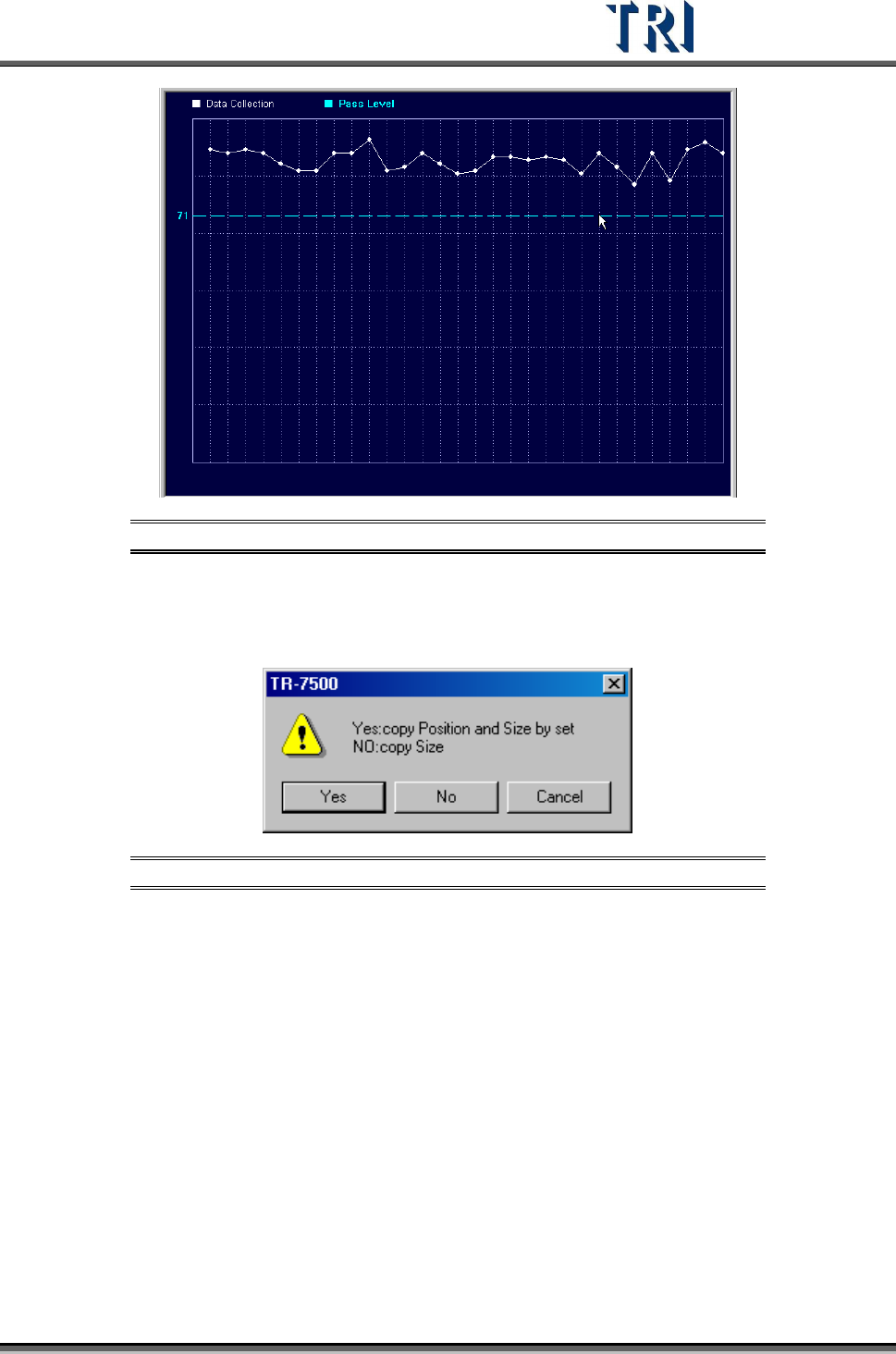
recent 30 data. Click on a data point to show the result. Drag the yellow line to
change the pass level (see following two figures).
Figure 418: Data Collection Chart 1 – Selecting Data Point
Test Research Inc.
TR7500 Series User Guide –Software v.2.9.0 251
Figure 419: Data Collection Chart 2 –Change Pass Level
11.6.2 Copy
Copy the size or position to the other components with same type.
Figure 420: Confirm Copy Size and/or Position
[Yes] – Copy the size and position to the related components on other boards in a
multi-board panel. If the inspection box is trained the setting can’t be changed.
[No] – Copy just the size to the other components.
11.6.3 Save Image
Save the FOV to the folder that the SOL file is saved in. The file name is composed by date
and time.
11.6.4 Set Fail String
Users can redefine the fail string of each inspection box. This is the same method used in
[Library].
Test Research Inc.
252 TR7500 Series User Guide –Software v.2.9.0
11.6.5 Set Weighting
The View Model widow shows [Set Weighting] is selected. Set the weighting for specified
image. See
11.9.2.6 for more information about “set weighting”.
11.6.6 Set Mask
Users can create a mask in [Void] or [Extra Blob].
11.6.7 Link Box
You can assign windows that are parents and children to link. See more about [Link] in 8.2.2
11.6.8 Unlink Box
Press [Unlink] to break the link between windows. See more about [Unlink] in 8.2.3
11.6.9 Copy Box
Copy the selected inspection box in the system.
11.6.10 Cut Box
Cut the selected inspection box.
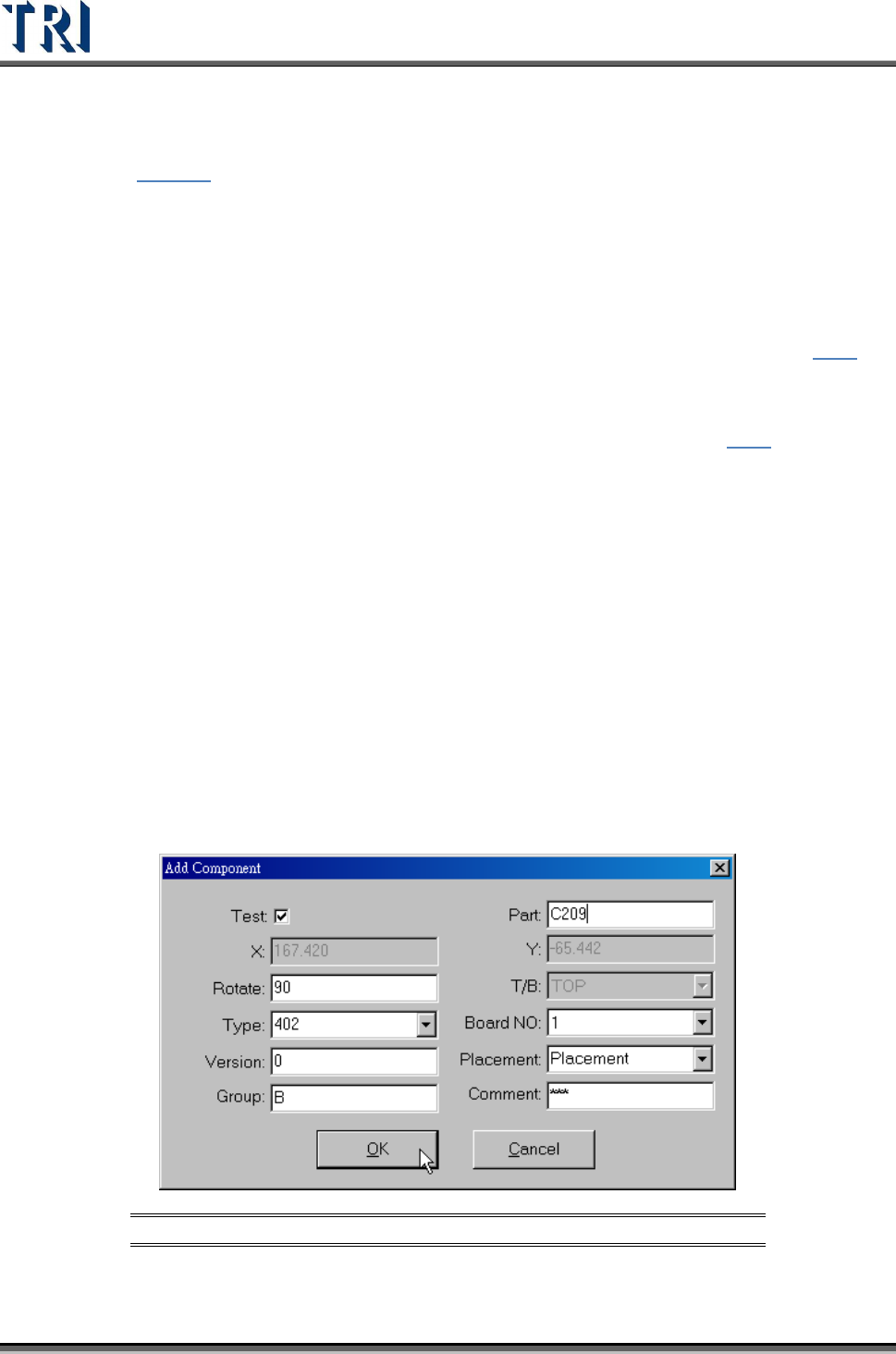
11.6.11 Paste Box
Paste the box that was chosen with the Copy or Cut command. Select a box and press Cut
Box or Copy Box first, then press Paste Box at the target FOV. The inspection box does not
appear right away: move the mouse to the correct position and left click on the image. The
dialog box shown below will appear. After the component information is input, press OK and
then the Pasted inspection box will become visible. If there are other components within
2mm of the newly-increased component, the inspection box cannot be inserted.
Figure 421: Add Component Dialog Box