TR7500_Series_Software_v29_En.pdf - 第24页
Test Research Inc. 2 TR7500 Series User Guide – Software v.2.9.0 2 AOI S TANDAR D P ROJECT C REATION The Automatic Test Program Generator (ATPG) is a pow erf ul tool incorporated into the TR7500 system. This chapter ex p…
Test Research Inc.
TR7500 Series User Guide –Software v.2.9.0 1
1 I
NTRODUCTION
Test Research Inc.’s (TRI) TR7500 series of high-speed, Automated Optical Inspection test
systems currently includes the TR7500, TR7500E, TR7500L, and TR7501. Desktop models
include the TR7500DT and TR7500DTL. They incorporate TRI’s Read-on-the-Fly™ scanning
for vibration-free imaging of Printed Circuit Boards and Assemblies (PCBs/PCBAs) . For
details of each model, please reference the relevant specification.
For purposes of convenience, this guide will use “TR7500” to refer to all models. This User
Guide—Software provides information on TR7500’s Software Features. Features which are
only for the non-DT models are specified as “TR7500 Series only”.
Test Research Inc.
2 TR7500 Series User Guide –Software v.2.9.0
2 AOI
S
TANDARD
P
ROJECT
C
REATION
The Automatic Test Program Generator (ATPG) is a powerful tool incorporated into the
TR7500 system. This chapter explains how ATPG works.
2.1 Project Creation & Start with ATPG
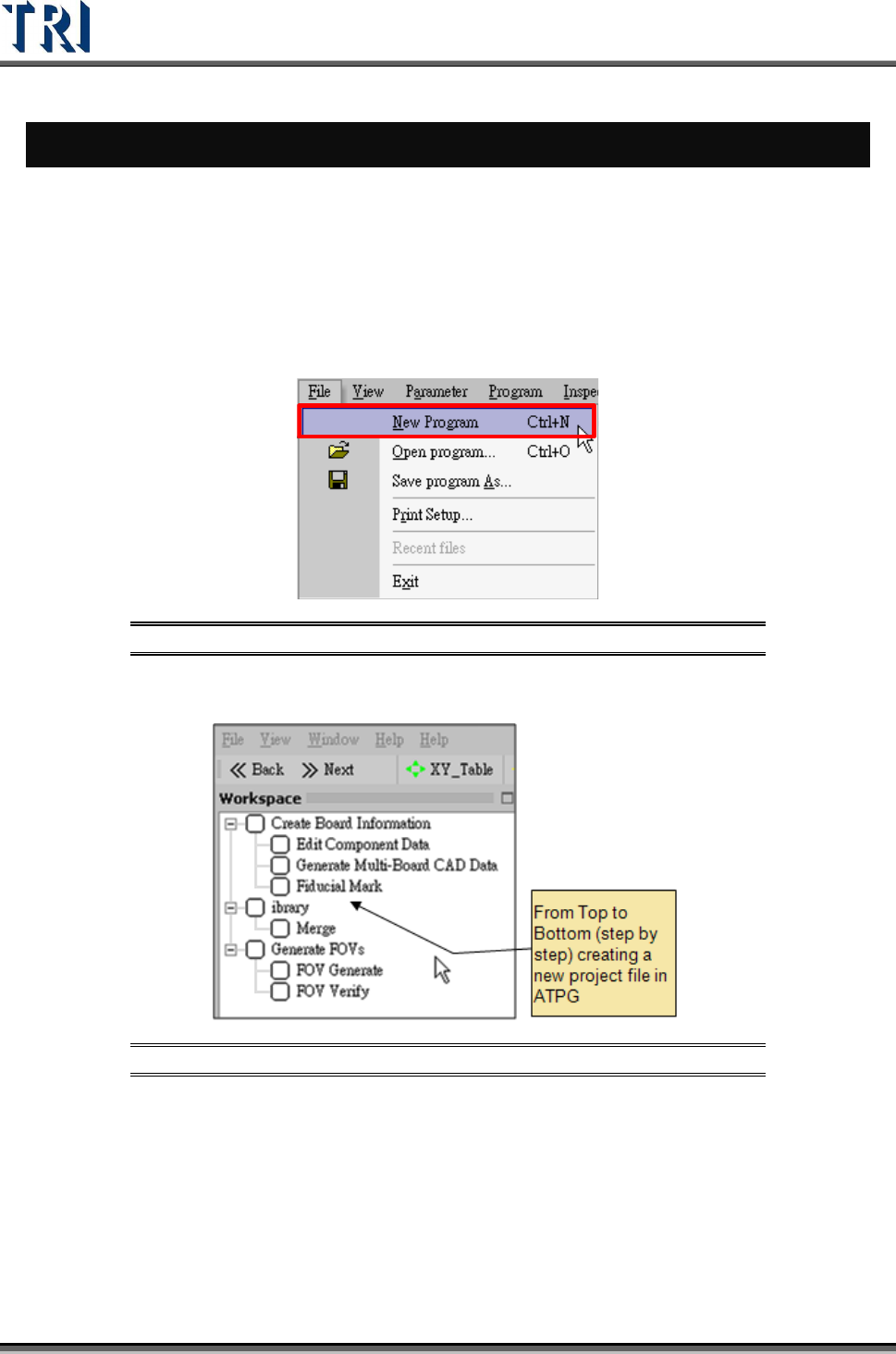
1. Double click on the shortcut of TR7500 main program.
2. Create a new project file.
Figure 1: Creating a New TR7500 Program File
3. ATPG steps appear.
Figure 2: List of ATPG Steps
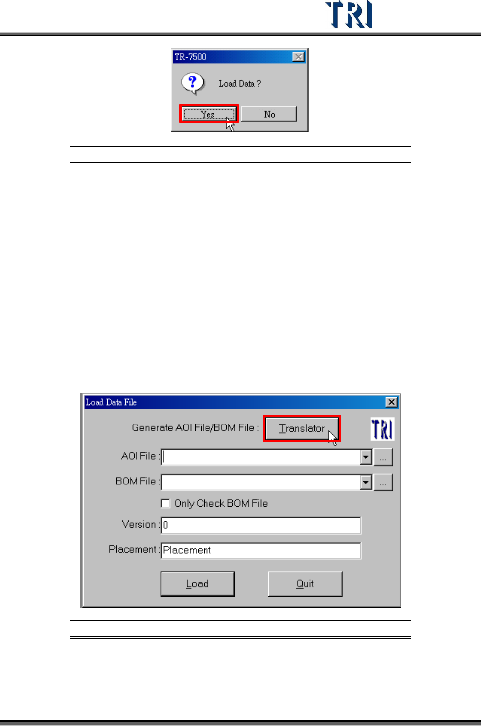
4. Confirm loading CAD file dialog window.
Test Research Inc.
TR7500 Series User Guide –Software v.2.9.0 3
Figure 3: Confirm Load Data Window
2.2 Create Board Information
For a new program, an AOI file (*.aoi) needs to be created first for the TR7500 to read. There
are two types of converters included with the system software: FABMaster and Default.
If there is a file named PARTS.ASC from the FABMaster program, it can be used by
FABMaster to transfer from ASC files to AOI file. Or all component data can be collected --
including component name, X and Y values, rotation angle, and type of component -- and
saved as a .TXT file. Transfer the data from the saved .TXT file to an AOI file by using the
DEFAULT translator. The [Component Name] field must be the characters, figures or
symbols which can be typed directly on the keyboard. The [Type] field must be the
characters or figures which can be typed directly on the keyboard or underline symbol (“_”).
The system will be unable to display or save in the correct format when the content is not
correct.
2.3 Translate a CAD to an AOI file.
Figure 4: Load Data File -- Translator