TR7500_Series_Software_v29_En.pdf - 第59页
Test Research Inc. TR7500 Series User Guide – Software v.2.9.0 37 speed, but the arrange ment of FOVs w ill be set as a panel. That is, the parameters [By Set] cannot be appli ed in the pro ject. c. Review the Library of…
Test Research Inc.
36 TR7500 Series User Guide –Software v.2.9.0
b. [Auto Locating in Y-direction]– FOV location will be shifted in Y direction if it’s
necessary.
c. [Windows auto separated by cutting]– If an inspection window group is cut, it will
separate into two groups.
d. [Move Windows in the Edge of FOV]–This item is to move inspection boxes that
are located within 30 pixels of the FOV edges to the neighboring FOV. This to
dispose the inspection box at the center as far as possible.
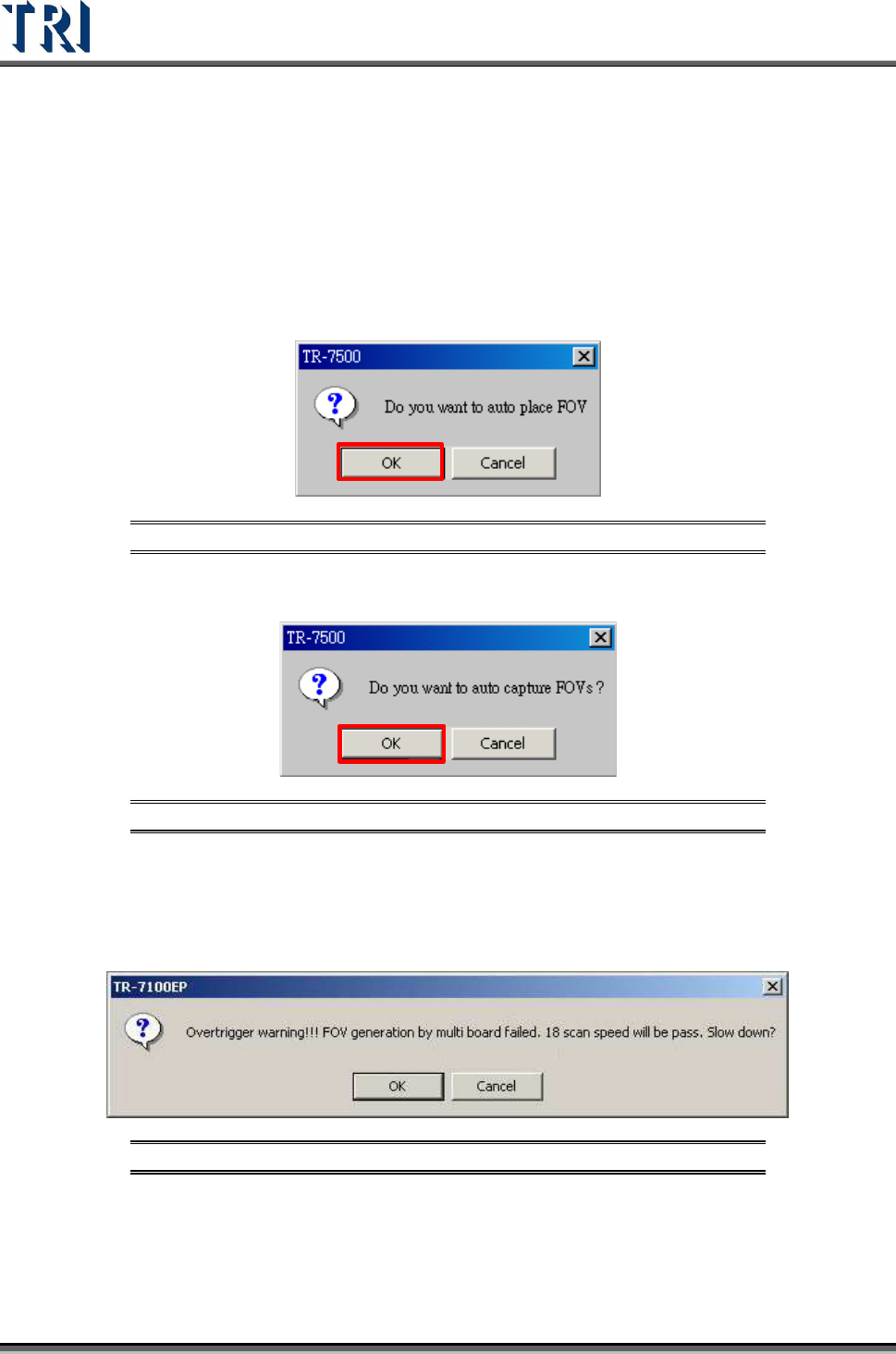
2. Warning message for auto-place inspection FOV.
Figure 61: Confirm Auto-Place FOV
3. Create the panel FOV image.
Figure 62: Confirm Auto-Capture of Panel FOVs
4. If there is a gap between boards and there are components laid on the edge of the
boards, the space between FOVs will be too close. The system has to slow down to
keep generating FOVs following the multi-board rule. The following window will appear.
There are three possible selections.
Figure 63: FOV Generate Warning
a. Selecting [OK] means scanning and inspecting the panel with the lower speed that
system suggests. The FOVs will be arranged originally, but the inspection time will
be longer.
b. Selecting [Cancel] means scanning and inspecting the panel with the original
Test Research Inc.
TR7500 Series User Guide –Software v.2.9.0 37
speed, but the arrangement of FOVs will be set as a panel. That is, the parameters
[By Set] cannot be applied in the project.
c. Review the Library of the component that is on the edge on an FOV. Try to reduce
the size of the inspection box and see if the problem will be solved.
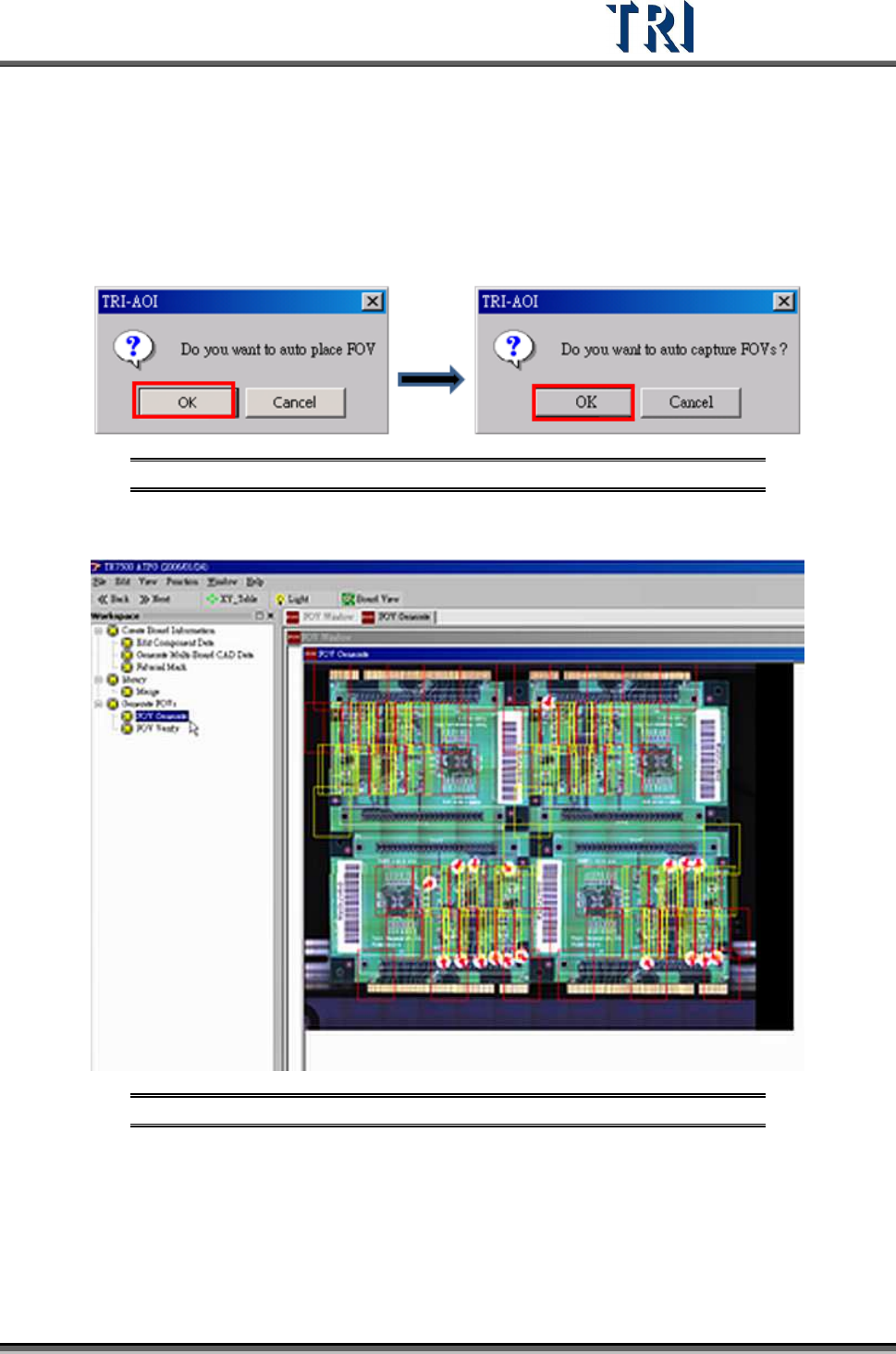
5. Warning message for auto place inspection FOV. Click [OK].
6. Auto-capture FOVs. Click [OK]. The panel FOV image will be created.
Figure 64: Confirm Auto-Place & Auto-Capture FOVs
7. Display every FOV’s position in the panel.
Figure 65: Display All FOVs
8. Go to next step.
9. Confirm window close. Click [OK].
Test Research Inc.
38 TR7500 Series User Guide –Software v.2.9.0
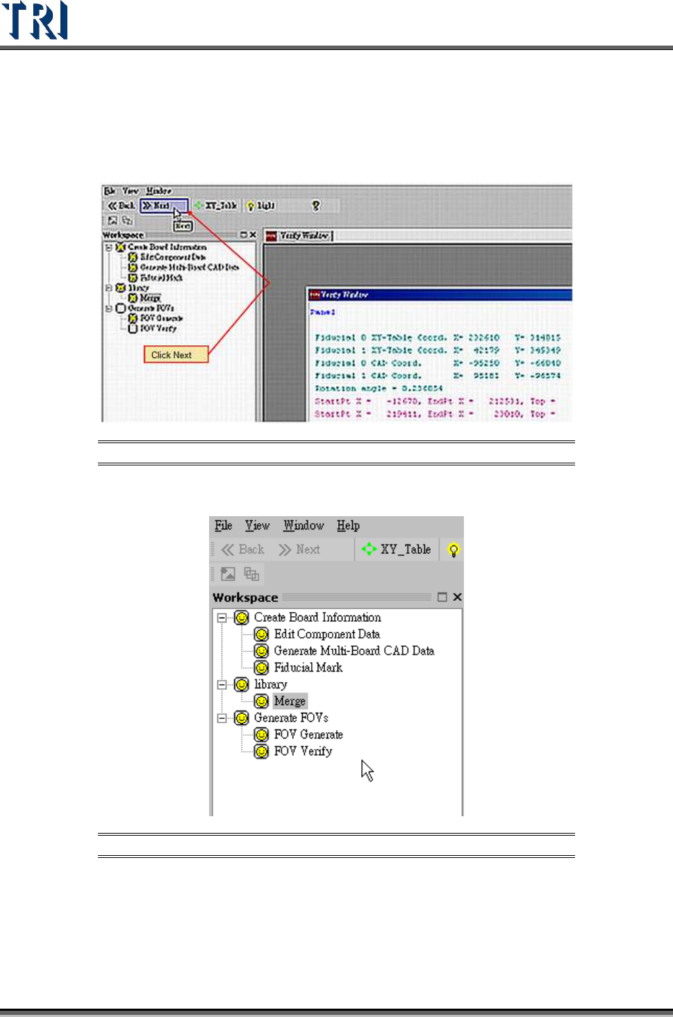
2.11 FOV Verify
1. Click the next button and go to next FOV verify process.
Figure 66: FOV Verify Main Window
2. When the all processes are finished, close the window to go to the Train process.
Figure 67: Complete ATPG Process
2.12 Train
1. Press [Train] to enter the Train dialog.