TR7500_Series_Software_v29_En.pdf - 第258页
Test Research Inc. 236 TR7500 Series User Guid e –Softwa re v.2.9.0 9.3 Color C heck Method and RGB We ighting 9.3.1 Color Check Method The Top-View camera consists of three CCD light-sensors . Unlike monoc hrom e camera…
Test Research Inc.
TR7500 Series User Guide –Software v.2.9.0 235
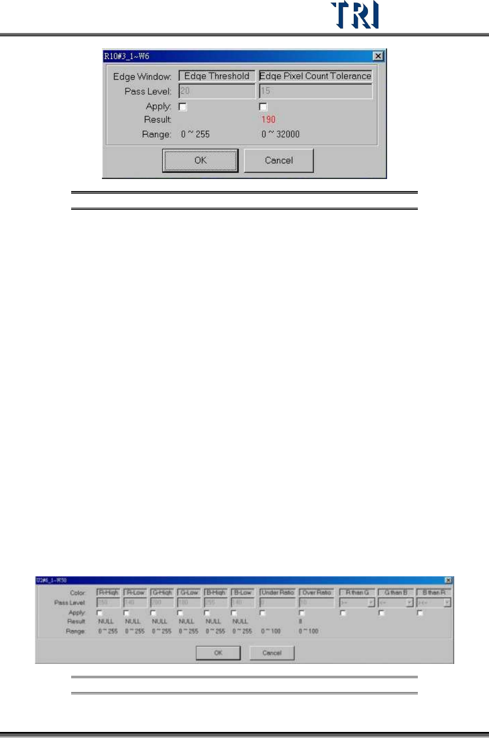
Figure 392: Edge Window Dialog
[Edge Threshold] – The difference of adjacent pixels
[Edge Pixel Count Tolerance] – The system will count all the pixels included by the
[Edge Threshold], and show “Fail” if the count is over the [Edge Pixel Count Tolerance]
9.2.13 Color Window
This function calculates the ratio of different colors found in a specific color.
The condition of Pixels’ R, G and B Value within the inspection box
[R-High] >= [R value] > [R-Low]
[G-High] >=
[G value] > [G-Low]
[B-High] >=
[B value] > [B-Low]
To meet the R than G,G than B,B than R conditions
Conditions
If (R ><=G), then ignore R&G relation //default
If (R >=G), then
[R value] >= [G value] + ([R-Low]-[G-Low])
If (R <=G), then
[R value] <= [G value] + ([R-Low)-[G-Low))
If (G ><=B), then don’t care G&B relation //default
If (G>=B), then
[G value] >= [B value] + ([G-Low]-[B-Low])
If (G <=B), then
[G value] <= [B value] + ([G-Low)-[B-Low))
If (B ><=R), then don’t care B&R relation //default
If (B >=R), then
[B value] >= [R value] + ([B-Low]-[R-Low])
If (B <=R), then
[B value] <= [R value] + ([B-Low]-[R-Low))
Areas which are over the [Over Ratio] or under [Under Ratio] are “Fail”.
Figure 393: Color Window Pass Levels
Test Research Inc.
236 TR7500 Series User Guide –Software v.2.9.0
9.3 Color Check Method and RGB Weighting
9.3.1 Color Check Method
The Top-View camera consists of three CCD light-sensors. Unlike monochrome cameras,
they tend to have much better contrast in images by regulating the RGB Weighting.
Inspection boxes that are specially created using the top CCD camera will have better quality
sample images, and better to use for comparisons. Hence, the camera can easily detect
major contrasts on failing components. This is called CCM (Color Check Method).
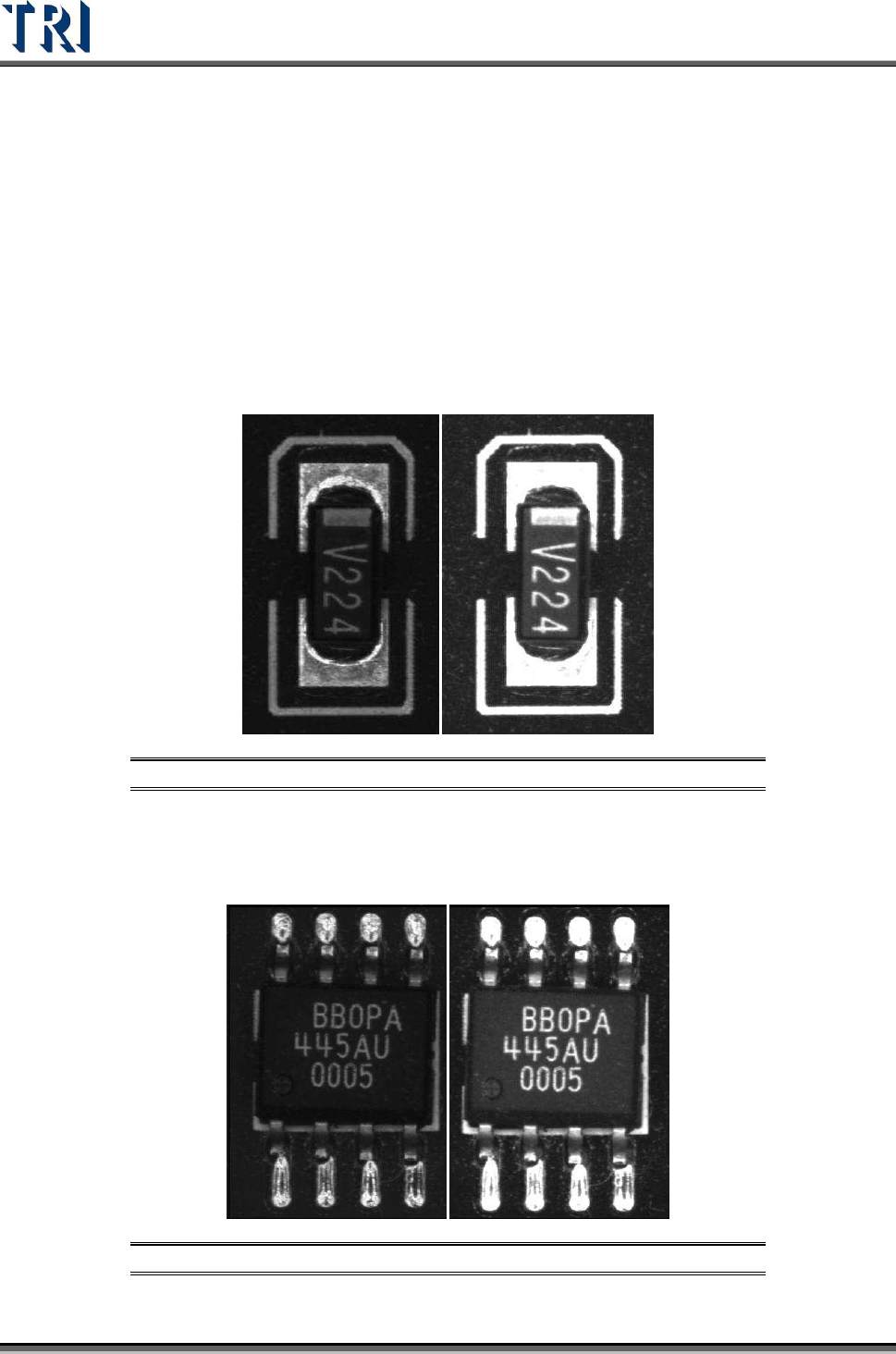
Using a resistor chip as an example, the image to the left was captured by a monochrome
camera, and the image to the right was captured by a three color sensor CCD camera and
regulated by RGB Weighting.
Figure 394: Resistor: Monochrome Image (left) & 3-Color CCD Image
Using an SOP designator as an example, the image to the left was captured by a
monochrome camera, and the image to the right was captured by a three color sensor CCD
camera and regulated by RGB Weighting.
Figure 395: SOP Designator: Monochrome Image (left) & 3-Color CCD Image
Test Research Inc.
TR7500 Series User Guide –Software v.2.9.0 237
Referring to the previous examples, the surface shape and lighting angles on solder joints
may have great impact on the image quality. Therefore, images that are captured by
monochrome cameras have irregular gray scale levels on solder joints. Images that are
captured by three color sensor CCD cameras regulated by RGB Weighting reflect much
better contrast which gives more stability to the inspection boxes.
9.3.2 RGB Weighting Dialog
Percentage input is used for RGB Weighting parameter settings. Increasing/decreasing the R,
G, or B settings will obtain the desired contrast for inspection purposes. This can also
eliminate unwanted color reflected by the boards for a better detection accuracy.
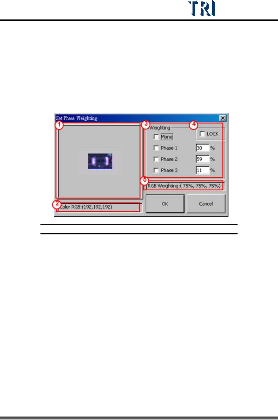
Figure 396: RGB Weighting Dialog
(1) Click on displayed image to zoom in.
(2) Display RGB or Grayscale level values.
(3) Options and settings for RGB Weighting by percentage.
(4) Check [LOCK] box to save the RGB setting as the default settings. [OK] must be
clicked to change the current RGB settings.
(5) Display RGB Weighting as percentages.
9.3.3 Example for TR7500 RGB Weighting
Using a missing designator as an example. The two figures below are in color and
monochrome. Within the monochrome figure, a placed designator and missing designator
locations are surrounded by red frames. The problem with the missing designator location is
that the software can easily mistake it for having a similar base color compared to an actual
placed designator’s body color. The picture to the left was taken by TR7500’s top color CCD
camera. The picture on the right was taken by a monochrome camera.