TR7500_Series_Software_v29_En.pdf - 第277页
Test Research Inc. TR7500 Series User Guide – Software v.2.9.0 255 Figure 426 : Rotate Control Bo Process 11.6.26 Present Win The control box w ill m ove to the cente r using the default size. 11.6.27 ICT Test Forces a c…
Test Research Inc.
254 TR7500 Series User Guide –Software v.2.9.0
Figure 423: Train Dialog -- Test Function Options
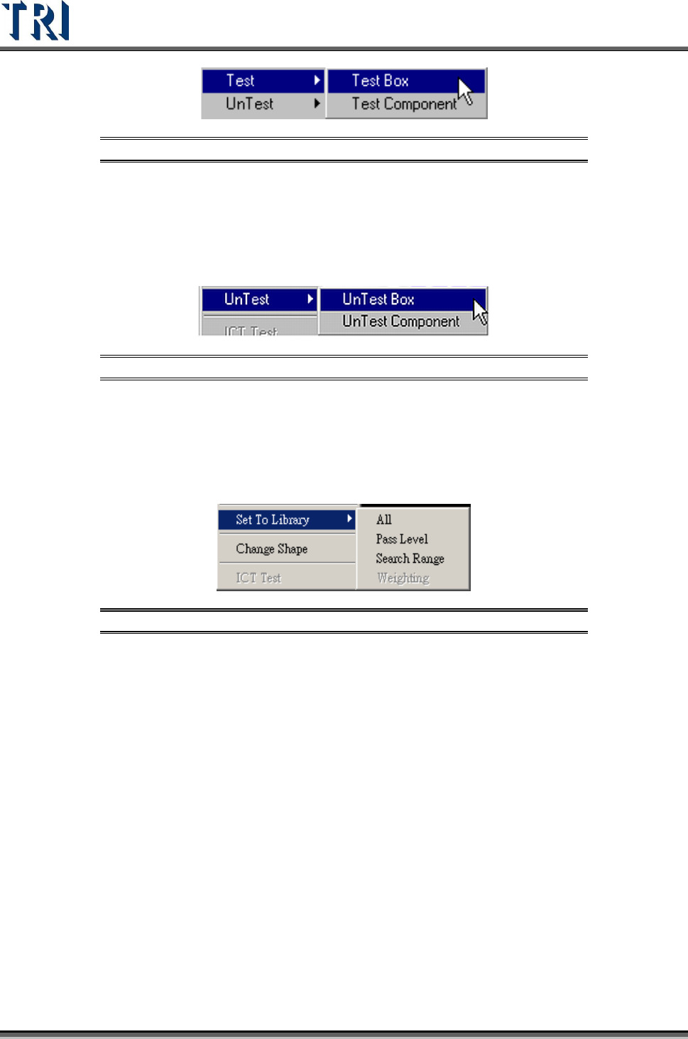
11.6.21 Untest
Set the selected inspection box as [UnTest Box] or [UnTest Component]. [UnTest Box]
means only set the selected box as untested and the box become blue; [UnTest Component]
means set all the boxes of the selected component as untested and the boxes become gray.
Figure 424: Train Dialog -- UnTest Function Options
11.6.22 Set to Library
Send the selected box’s information of [Pass Level] or [Search Range] to the [Library]. Select
only the inspection boxes that belong to a single component. [Weighting] is only for TR7500
series.
Figure 425: Set to Library Menu
11.6.23 Change Shape
The function is to change the window shape from square to circle or from circle to square. It
only works for [Void] or [Solder] windows.
11.6.24 Send .BMP to Repair Station
Send the alternative .BMP image from the selected [Missing] box to [Repair Station]. The
purpose is to preserve a better image of small components.
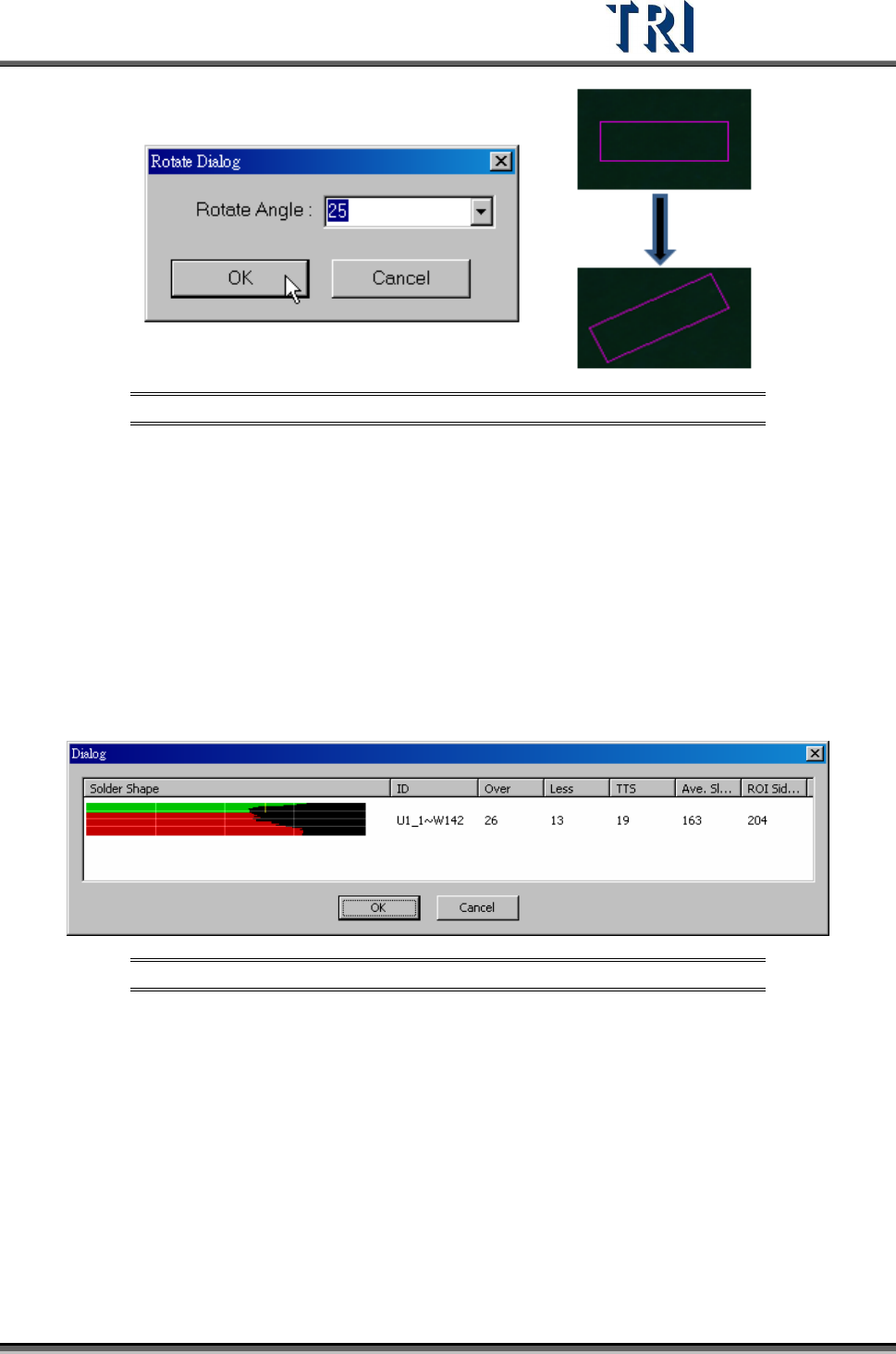
11.6.25 Set Control Box Angle
Rotate the control box manually. Refer to the following figure.
Test Research Inc.
TR7500 Series User Guide –Software v.2.9.0 255
Figure 426: Rotate Control Bo Process
11.6.26 Present Win
The control box will move to the center using the default size.
11.6.27 ICT Test
Forces a component to be tested by ICT.
11.6.28 Solder Shape Test
Display the solder inspection analyst result, as shown in the following figure. Only for the
TR7500 series.
Figure 427: Display Solder Shape
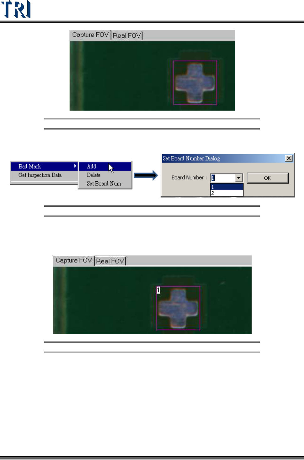
11.6.29 Bad Mark
Under [Train] users may right-click the mouse to add bad marks in an FOV. The system will
detect the bad mark each time, and the board will be labeled as [Skip] once the bad marks
fail. For more than one bad mark on the board, any of the bad marks will result in the board
labelled as [Skip]. Setting a bad mark will not decrease the inspection cycle time.
1. Move the control box on the taget point to set as a [Bad Mark].
Test Research Inc.
256 TR7500 Series User Guide –Software v.2.9.0
Figure 428: Set Bad Mark - 1
2. Right click mouse to add a [Bad Mark]
Figure 429: Bad Mark Dialog
3. Select the board number
4. The [Bad Mark] will show the board number inside of inspection box
Figure 430: Set Bad Mark - 2
5. Users may change the search range, image, and parameters of a [Bad Mark].
6. Under [Train] window, users may search for a [Bad Mark] by using [Find FOV by
Type/Name] and selecting [Bad Mark] under [Type].
7. Users may change the [Bad Mark] inspection box to inverse logic by right-clicking the
mouse on the inspection box and selecting [Inverse Logic].