TR7500_Series_Software_v29_En.pdf - 第327页
Test Research Inc. TR7500 Series User Guide – Software v.2.9.0 305 A PPEN DIX 1 L IGHT ING C OMP ENSATI ON 1. Lighting Compensa t ion This function uses so f tware to per f orm lighting compensatio n for every camera. Th…
Test Research Inc.
304 TR7500 Series User Guide –Software v.2.9.0
6. Press [Confirm PASS] or [Confirm FAIL] then this data is canceled and the next result
appears.
7. When the settings are changed at the Offline Editor, the system saves a [*.fbk] file in the
[AOI_Offline_Data] folder. When AOI is transferring data to the Offline Editor, it reviews
the [*.fbk] file at the same time and the inspection parameters are modified at the next
inspection.
15.4.3.2 Train Dialog
1. Press [Train] to enter the [Train] dialog.
2. Click on an inspection box to review the result.
3. Right click on the inspection box and select [V
IEW
>
S
HOW
D
ATA
C
OLLECTION
C
HART OF
THIS
B
OX
]. The system shows the latest 1000 data of this box.
4. Change the search range, pass level or add an alternative image in this window.
Test Research Inc.
TR7500 Series User Guide –Software v.2.9.0 305
A
PPENDIX
1
L
IGHTING
C
OMPENSATION
1. Lighting Compensation
This function uses software to perform lighting compensation for every camera. The standard
is that when the lighting range is established as 60mA and the intensity is 128 at all adjusted
zones, the gray level of the gray card image is compensated to 100.
1. Press [S
TART
>
R
UN
]. Key in “regedit” to open the registry. Enter
“HKEY_LOCAL_MACHINE\HKEY_LOCAL_MACHINE\SOFTWARE\TRI\” and check if
there is a DWORD variable named “LightingCompensation”. If the variable does not exist,
open the main program of TR7500 and the variable is created automatically.
2. To execute lighting compensation, change the value of the variable to “1”.
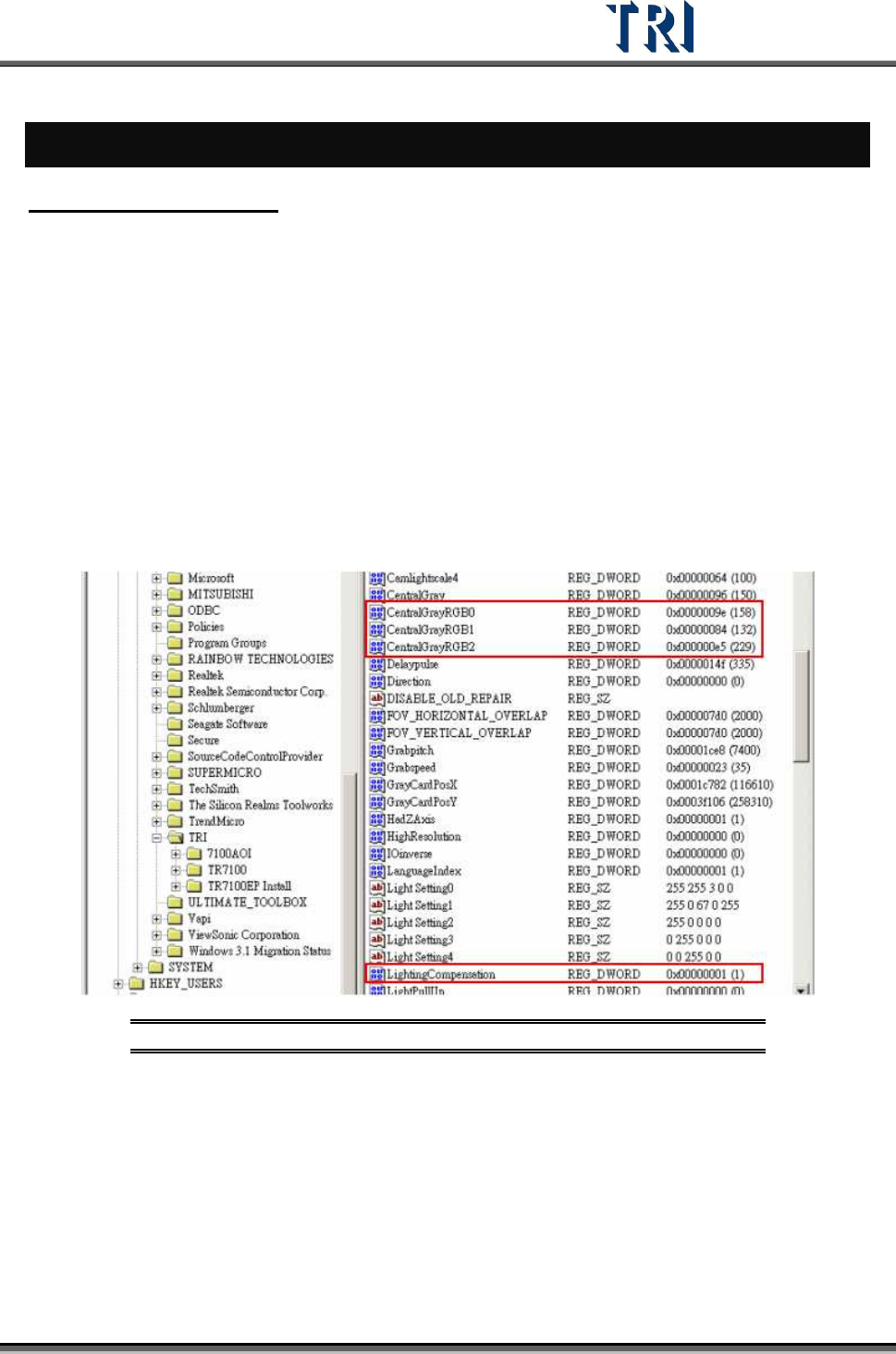
3. The first time the lighting is executed, the system creates the following four parameters:
[Central/Gray] – the objective gray level for the four side-view cameras -- and
[CentralGrayRGB0], [CentralGrayRGB1], and [CentralGrayRGB2] -- the objective gray
level for R, G, B sensors.
Figure 499: Lighting Compensation Parameters
4. Open the TR7500 main program of and enter [U
TILITIES
>
C
AMERA
A
LIGNMENT
].
Test Research Inc.
306 TR7500 Series User Guide –Software v.2.9.0
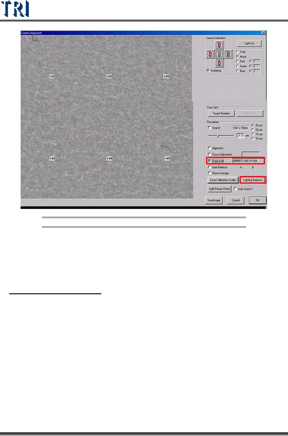
Figure 500: Camera Alignment Dialog
5. Move the X-Y table to position the camera above the gray card. Or press [MoveTo]
button.
6. Select the [GrayLevel] to show the gray level of the current image.
7. Click on the [Lighting Balance] button and input the password “7100” to do lighting
compensation. (Note: Be sure that the FOVs of 5 cameras are on the gray card.)
2. Lighting Decay Auto Check
This function uses software to test the difference between the current value (before
compensating) and the objective value for all five cameras.
1. Open the main program of TR7500 and enter [U
TILITIES
>
C
AMERA
A
LIGNMENT
].
2. Move the X-Y table to let the camera above the center of gray card.
3. Press [Light-Decay Check].
4. For the first time, the system displays the window below to ask if you want to save the
position of the gray card to system. The value of the X-coordinate and Y-coordinate are
saved in the registry and named “GrayCardPosX” and “GrayCardPosY”. When the two
variables exist, the window below does not appear again. To change the value, move the
cameras to be on the gray card then click on the [Teach Position] button.