TR7500_Series_Software_v29_En.pdf - 第215页
Test Research Inc. TR7500 Series User Guide – Software v.2.9.0 193 Figure 326 : Model Library Dialog 3. W hen the mouse cursor i s rolled over an icon , a label appears w ith compon ent type and kind. Refer to the figure…
Test Research Inc.
192 TR7500 Series User Guide –Software v.2.9.0
8.6.8.2 Model Library Usage
Under the [Library] window, users select the component and [T
OOL
>
M
ODEL
L
IBRARY
].
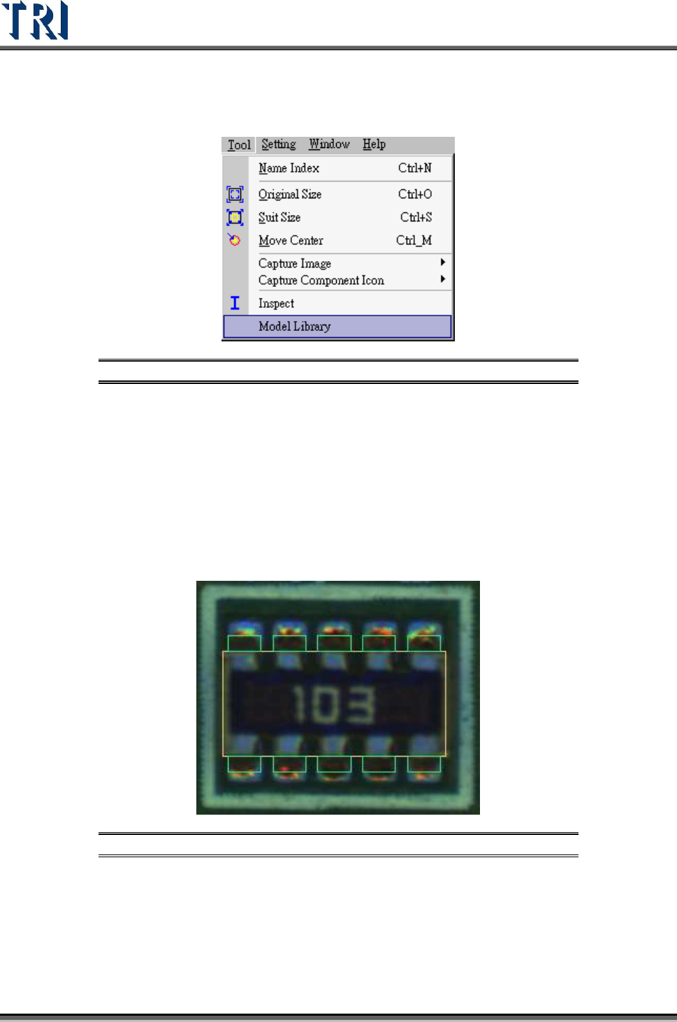
Figure 324: Model Library Command
Users need to create [Body] and [Pin] windows for “R-Net”, “C-Net”, “SOT”, “TO”, “IC” and
“DIP” types. For other component types only the [Body] window needs to be created.
After completing the [Body] and [Pin] boxes, the system will apply the corresponding
inspection boxes with the selected [Model].
8.6.8.3 Model Library Procedure
1. Users need to add all the [Body] and [Pin] boxes for the selected [Type] under the
[Library] window.
Figure 325: Body & Pin Boxes
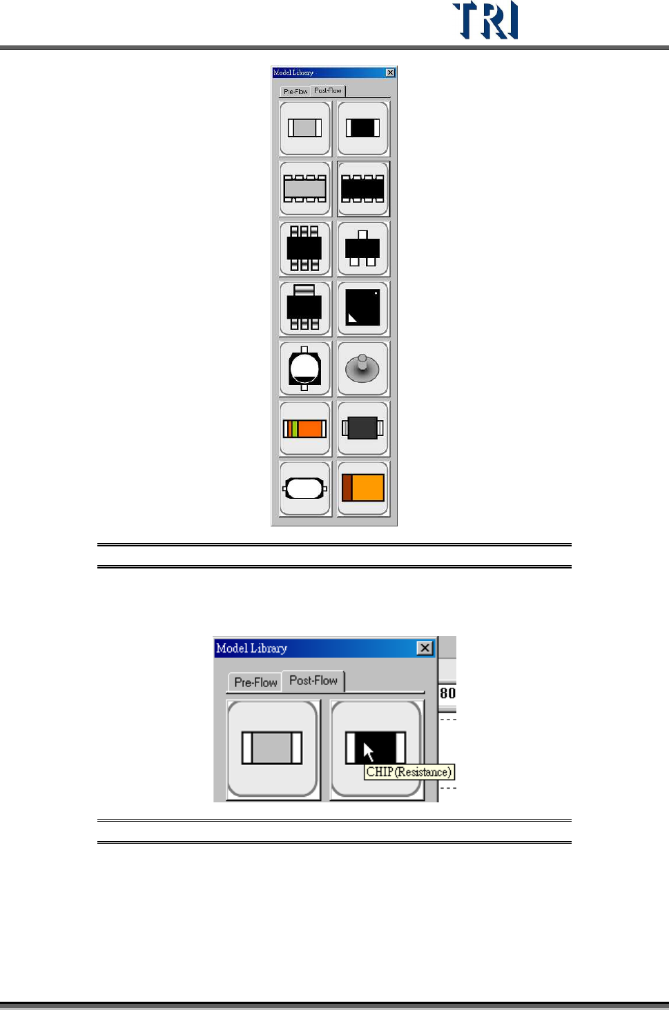
2. Select [T
OOL
>
M
ODEL
L
IBRARY
]. The [Model Library] dialog will appear.
Test Research Inc.
TR7500 Series User Guide –Software v.2.9.0 193
Figure 326: Model Library Dialog
3. When the mouse cursor is rolled over an icon, a label appears with component type
and kind. Refer to the figure below.
Figure 327: Example – Icon Label
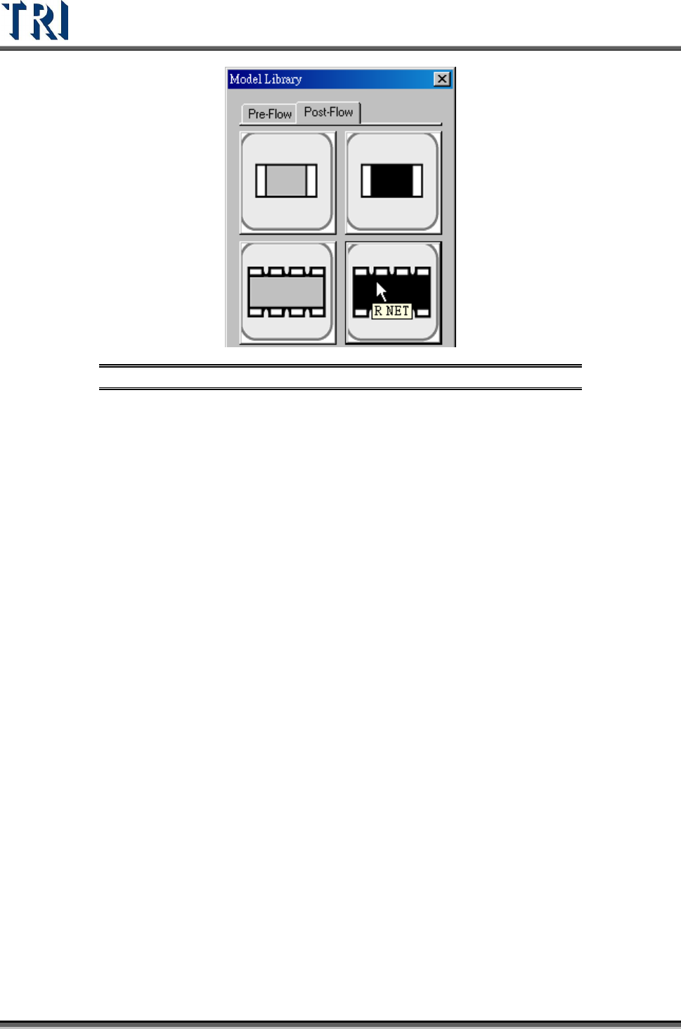
4. Select the default model. Use [R NET] for this example.
Test Research Inc.
194 TR7500 Series User Guide –Software v.2.9.0
Figure 328: Select Default Model
5. The system then will apply the saved inspection boxes on to those [Body] and [Pin]
boxes. The locations and sizes are determined by [Body] and [Pin] settings.
6. While applying those boxes, the system will use [Body Size] as a condition and search
in the [Library] for matches. The system will open a [Component Library Dialog] when
it finds a matching size. Users may decide to apply the existing model under the
[Component Library] or use the [Model Library] to create a new one.