TR7500_Series_Software_v29_En.pdf - 第250页
Test Research Inc. 228 TR7500 Series User Guid e –Softwa re v.2.9.0 Figure 380 : Lead Pass Leve l Settings [Si m ilarity] – The similarity between the standard image and the inspected image. [Shi f t X] – The toleran…
Test Research Inc.
TR7500 Series User Guide –Software v.2.9.0 227
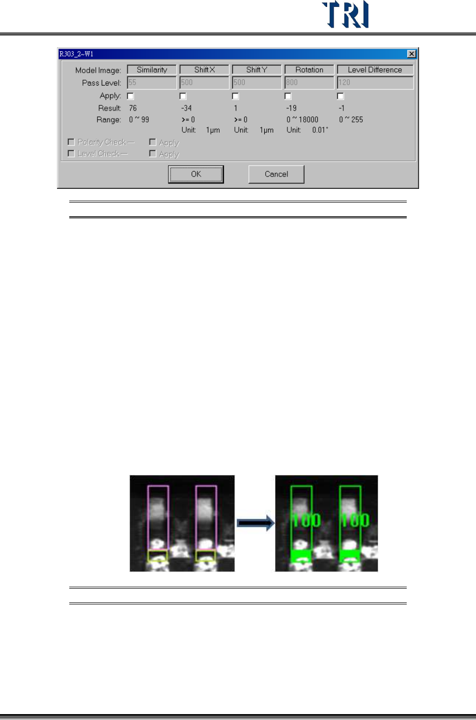
Figure 378: Model Image Pass Level Settings
[Similarity] – The similarity between standard image and inspected image.
[Shift X] – The tolerance of shift on x direction.
[Shift Y] – The tolerance of shift on y direction.
[Rotation] – The tolerance of rotate angle
[Level Difference] – System will save the gray level average of a 10x10 pixel
area at the center of the box for inspecting. For example, if the trained value is
100 and the level difference tolerance is 35. It means the system will show fail
when the result is over 135 or less than 65.
[Polarity Check] – If the component is rotated 180 degrees it will be judged as a
defect.
[Level Check] – Select to open the [Level Difference] function.
9.2.2 Lead
Checks missing, shift and bending of IC leads. Use image correlation method (Method2).
grab a good image model for sample. Compare with test lead to find the
defect.
Figure 379: Compare Lead Images
The [Pass Level Settings] are shown in the following figure.
Test Research Inc.
228 TR7500 Series User Guide –Software v.2.9.0
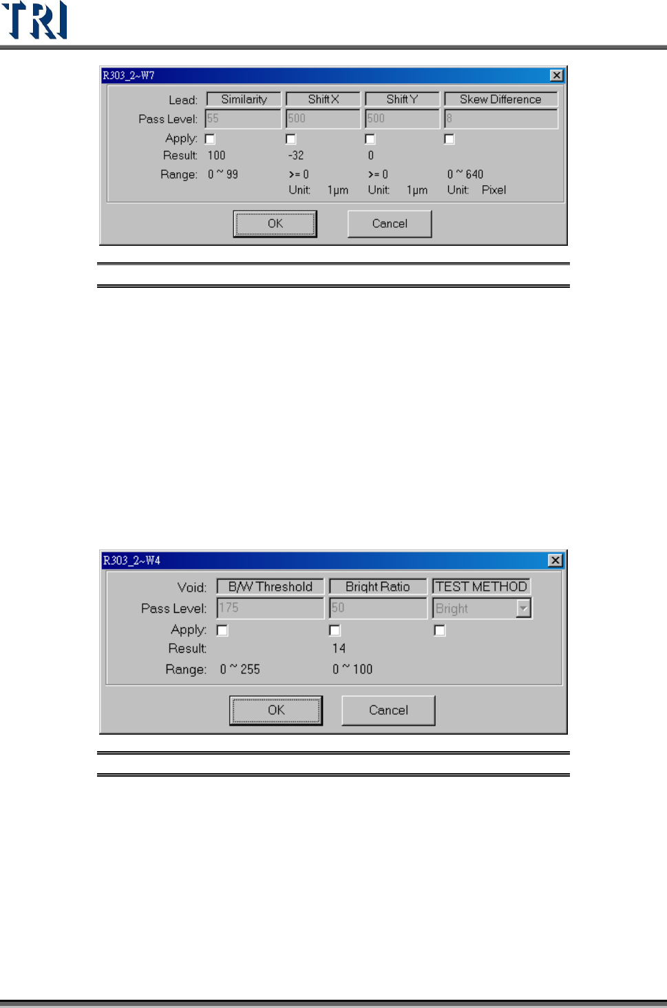
Figure 380: Lead Pass Level Settings
[Similarity] – The similarity between the standard image and the inspected image.
[Shift X] – The tolerance of shift on X direction.
[Shift Y] – The tolerance of shift on Y direction.
[Skew Difference] – The tolerance of position difference between adjacent boxes.
9.2.3 Void
Checks for no solder, open, and/or polarity of components. Uses the levels set in [B/W
Threshold] and [Bright Ratio] to find the defect. Bright/Dark is a method to find the
darkness/brightness.
The [Pass Level Settings] are shown in the following figure.
Figure 381: Void Pass Level Settings
[B/W Threshold] – Set the threshold to judge the black and white.
[Bright Ratio] – Set the tolerance of white ratio.
[TEST Method]
[Bright] – If the white ratio is over the tolerance, the inspection box will be
regarded as failed.
[Dark] –If the white ratio is lower than the tolerance, the inspection box will be
regarded as failed.
Test Research Inc.
TR7500 Series User Guide –Software v.2.9.0 229
9.2.4 Lead Void
Checks for no solder or open for IC leads. The algorithm is the same as for Void window.
The difference is not calculating the bright area as denominator when training the lead void.
The [Pass Level Settings] are shown in the following figure.
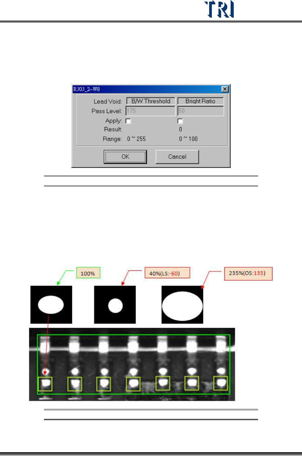
Figure 382: Lead Void Pass Level Settings
[B/W Threshold] – Set the threshold to judge the black and white.
[Bright Ratio] – Set the tolerance of white ratio.
9.2.5 Pin
Checks the shift, over/ low solder, or open of components. Set [Threshold} and {High/Low
Ratio] to check NG or not. When user trains a pin window, the software will memorize the
bright zone as 100.
Figure 383: 100% & Low Solder, Over Solder Settings
The [Pass Level Settings] are shown in the following figure.