TR7500_Series_Software_v29_En.pdf - 第57页
Test Research Inc. TR7500 Series User Guide – Software v.2.9.0 35 Figure 59: Click Next, Finis h Library M erge, Proceed to Generate FOVs 2.10 FOV Genera te 1. Set the best FOV distrib ut ion rule for AOI inspection. Fig…
Test Research Inc.
34 TR7500 Series User Guide –Software v.2.9.0
2.8 Edit (Create or Modify a New) Component Library
See Chapter 8, Edit Component Library Commands
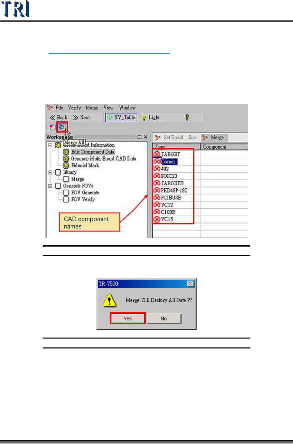
2.9 Merge with Component Library
Merge CAD file with component library (component has finished editing).
1. Select [Merge] button.
Figure 57: Select Merge Component Library
2. Warning message before merge component library.
Figure 58: Confirm Merge Function
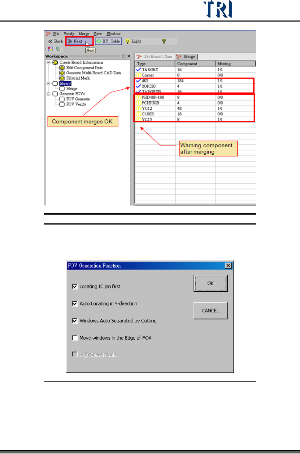
3. Merge finished. CAD device linked with component library.
4. Proceed to next step.
Test Research Inc.
TR7500 Series User Guide –Software v.2.9.0 35
Figure 59: Click Next, Finish Library Merge, Proceed to Generate FOVs
2.10 FOV Generate
1. Set the best FOV distribution rule for AOI inspection.
Figure 60: Set FOV Distribution Rules
There are four functions for FOV generation. The more check boxes selected, the
longer the generation process will take. The functions are:
a. [Locating IC pin first]– It will take fewer FOVs to merge with IC pin windows,
including LEAD and SOLDER.
Test Research Inc.
36 TR7500 Series User Guide –Software v.2.9.0
b. [Auto Locating in Y-direction]– FOV location will be shifted in Y direction if it’s
necessary.
c. [Windows auto separated by cutting]– If an inspection window group is cut, it will
separate into two groups.
d. [Move Windows in the Edge of FOV]–This item is to move inspection boxes that
are located within 30 pixels of the FOV edges to the neighboring FOV. This to
dispose the inspection box at the center as far as possible.
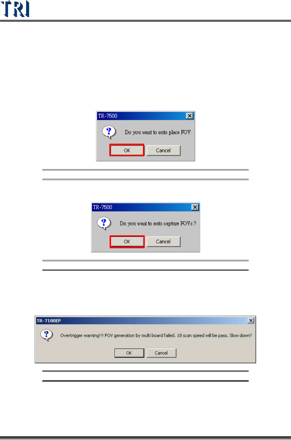
2. Warning message for auto-place inspection FOV.
Figure 61: Confirm Auto-Place FOV
3. Create the panel FOV image.
Figure 62: Confirm Auto-Capture of Panel FOVs
4. If there is a gap between boards and there are components laid on the edge of the
boards, the space between FOVs will be too close. The system has to slow down to
keep generating FOVs following the multi-board rule. The following window will appear.
There are three possible selections.
Figure 63: FOV Generate Warning
a. Selecting [OK] means scanning and inspecting the panel with the lower speed that
system suggests. The FOVs will be arranged originally, but the inspection time will
be longer.
b. Selecting [Cancel] means scanning and inspecting the panel with the original