TR7500_Series_Software_v29_En.pdf - 第275页
Test Research Inc. TR7500 Series User Guide – Software v.2.9.0 253 11.6.12 Move to Left FOV Move the selected box to the le f t FOV. 11.6.13 Move to Right FOV Move the selected box to the right F O V.. 11.6.14 Move All B…
Test Research Inc.
252 TR7500 Series User Guide –Software v.2.9.0
11.6.5 Set Weighting
The View Model widow shows [Set Weighting] is selected. Set the weighting for specified
image. See
11.9.2.6 for more information about “set weighting”.
11.6.6 Set Mask
Users can create a mask in [Void] or [Extra Blob].
11.6.7 Link Box
You can assign windows that are parents and children to link. See more about [Link] in 8.2.2
11.6.8 Unlink Box
Press [Unlink] to break the link between windows. See more about [Unlink] in 8.2.3
11.6.9 Copy Box
Copy the selected inspection box in the system.
11.6.10 Cut Box
Cut the selected inspection box.
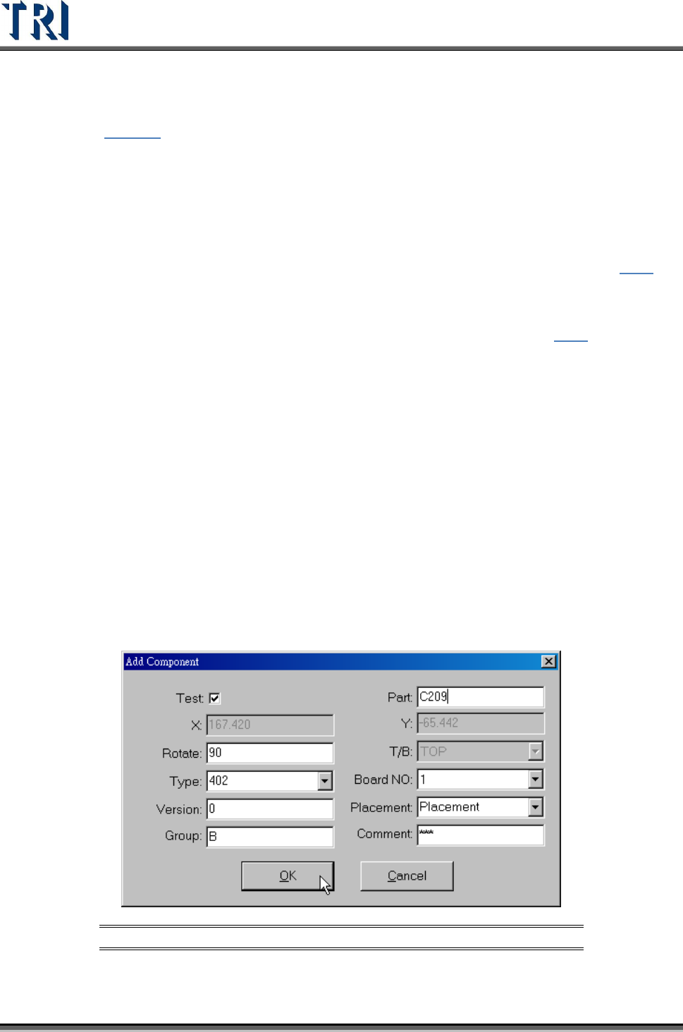
11.6.11 Paste Box
Paste the box that was chosen with the Copy or Cut command. Select a box and press Cut
Box or Copy Box first, then press Paste Box at the target FOV. The inspection box does not
appear right away: move the mouse to the correct position and left click on the image. The
dialog box shown below will appear. After the component information is input, press OK and
then the Pasted inspection box will become visible. If there are other components within
2mm of the newly-increased component, the inspection box cannot be inserted.
Figure 421: Add Component Dialog Box
Test Research Inc.
TR7500 Series User Guide –Software v.2.9.0 253
11.6.12 Move to Left FOV
Move the selected box to the left FOV.
11.6.13 Move to Right FOV
Move the selected box to the right FOV..
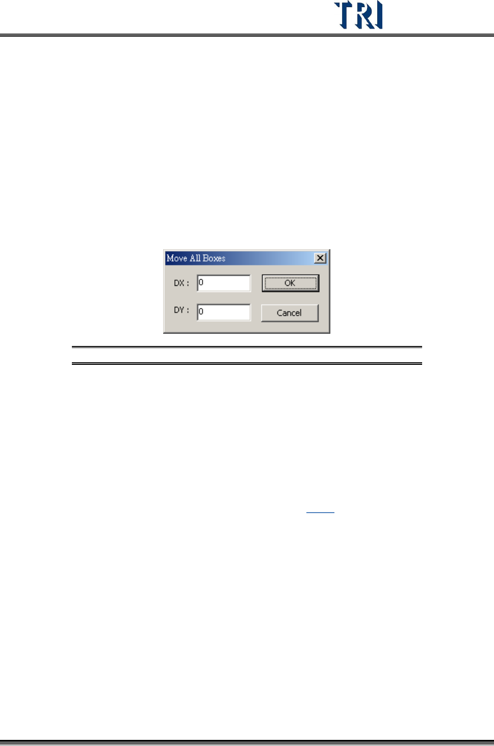
11.6.14 Move All Boxes
Users may move all the inspection boxes which are under the same camera at the same
time. The [Move All Boxes] dialog will appear (see following figure). Enter a positive value in
[DX] will send the camera to move right. Enter a positive value in [DY] will move the camera
down. However, some boxes will not move if they are about to be moved out of the FOV or
are on the edge of FOV within 8 pixels.
Figure 422: Move All Boxes Dialog
11.6.15 Undelete Box
Undelete the last deleted box by clicking this function.
11.6.16 Rotate Box Side
Each mouse click rotates the pin direction 90 degrees counterclockwise.
11.6.17 Set Logic
Set the [Logic] between windows. See more about logic in 8.7.1.
11.6.18 View Logic
11.6.19 Inverse Logic
Selecting this item starts the Inverse Logic function. After selecting this function, the system
regards a box that is passing the pass level as failed and a box that is not passing the pass
level as passed.
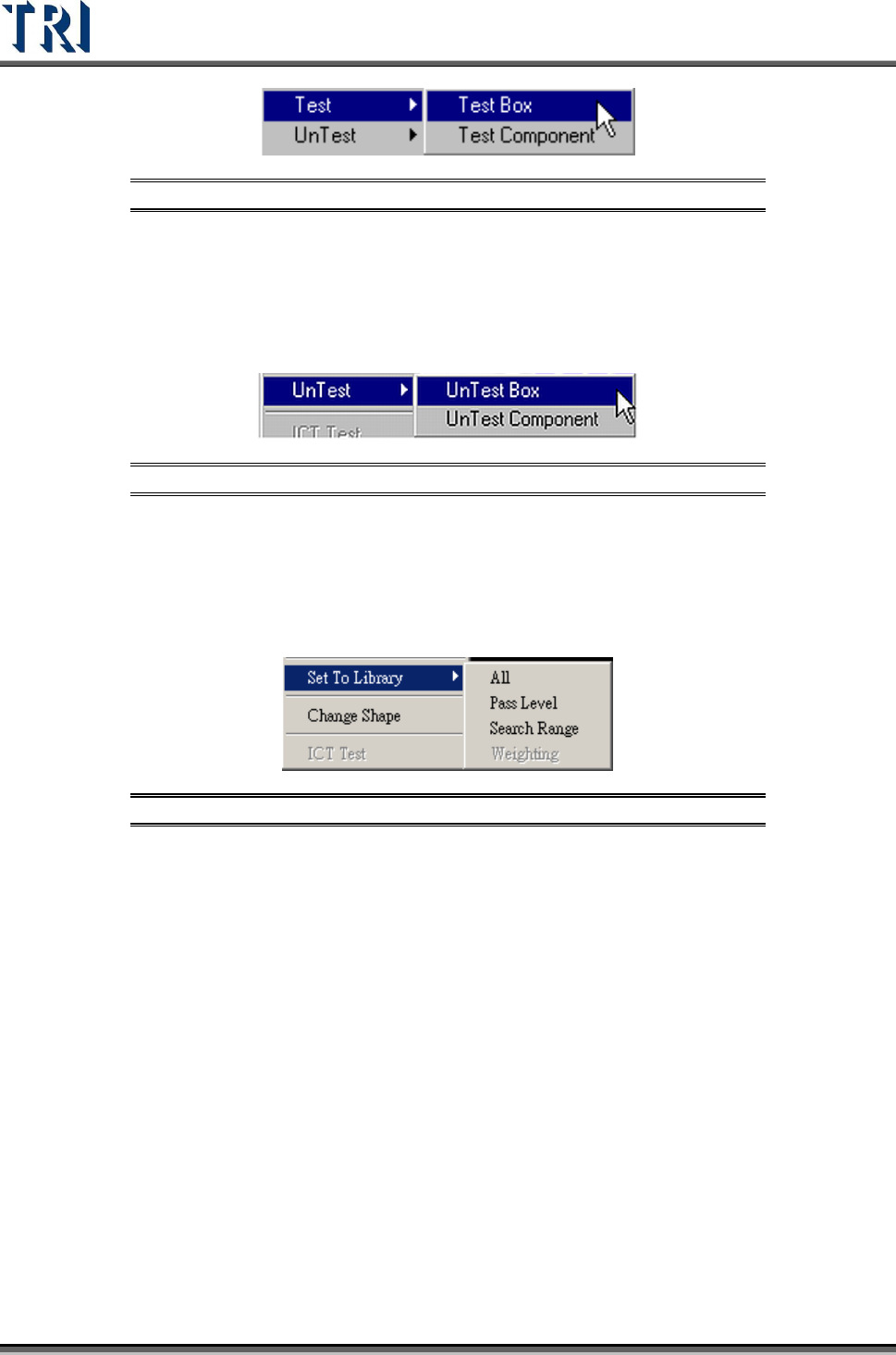
11.6.20 Test
Set the selected inspection box as [Test Box] or [Test Component].
Test Research Inc.
254 TR7500 Series User Guide –Software v.2.9.0
Figure 423: Train Dialog -- Test Function Options
11.6.21 Untest
Set the selected inspection box as [UnTest Box] or [UnTest Component]. [UnTest Box]
means only set the selected box as untested and the box become blue; [UnTest Component]
means set all the boxes of the selected component as untested and the boxes become gray.
Figure 424: Train Dialog -- UnTest Function Options
11.6.22 Set to Library
Send the selected box’s information of [Pass Level] or [Search Range] to the [Library]. Select
only the inspection boxes that belong to a single component. [Weighting] is only for TR7500
series.
Figure 425: Set to Library Menu
11.6.23 Change Shape
The function is to change the window shape from square to circle or from circle to square. It
only works for [Void] or [Solder] windows.
11.6.24 Send .BMP to Repair Station
Send the alternative .BMP image from the selected [Missing] box to [Repair Station]. The
purpose is to preserve a better image of small components.
11.6.25 Set Control Box Angle
Rotate the control box manually. Refer to the following figure.