TR7500_Series_Software_v29_En.pdf - 第204页
Test Research Inc. 182 TR7500 Series User Guid e –Softwa re v.2.9.0 Figure 306 : Adding a Pin w ith the Pin Box Function If you select 2 pins and press [Pin], the followin g dialog will appear. Input the total number o f…
Test Research Inc.
TR7500 Series User Guide –Software v.2.9.0 181
8.4.1 Body
The system will get the size and position of components by using the Body box. Creating a
Body box also can help for editing the library.
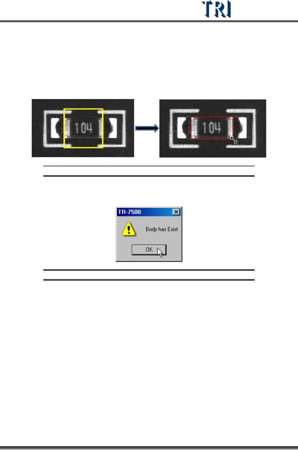
Press [Add > Body] and the system will create a square, yellow Body Box. Adjust the size of
the Body Box by clicking and dragging the mouse. Move the position of the box to the
component center by [Motion Control] dialog.
Figure 304: Adding a Body Box
Only one Body window is allowed for each component. If the Body already exists and you
also press [Body] the following window will appear. Press [OK].
Figure 305: Existing Body Box Warning Message
8.4.2 Pin
Use of the Pin Box lets the system get the size, position and number of IC pins. Creating a
Pin Box also can help for editing the library.
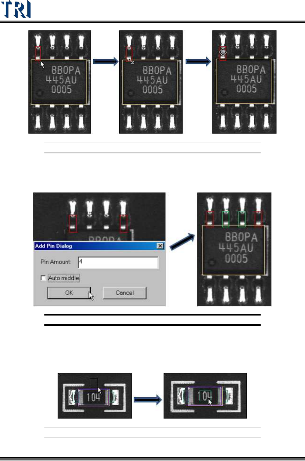
Press [Add > Pin], then click and drag the mouse to create a Pin Box. The initial position of
clicking must be at the same side with IC pin against body window because the system
judges the position of IC pins by initial clicking. If a pin is created at one side of the body then
moved to another side, the system will make mistakes later.
Adjust the size and position to match the IC lead.
Test Research Inc.
182 TR7500 Series User Guide –Software v.2.9.0
Figure 306: Adding a Pin with the Pin Box Function
If you select 2 pins and press [Pin], the following dialog will appear. Input the total number of
pins and press [OK]. The system will create the pins by interpolation. When you check [Auto
middle] all the pins will move against the middle of body.
Figure 307: Adding 4 Pins with the Pin Box Function
8.4.3 Window
Choose [Add > Window] to create a Void Window. Then move the window to the correct
position.
Figure 308: Adding Void Window with Add Window Function
Test Research Inc.
TR7500 Series User Guide –Software v.2.9.0 183
The settings of this window are [TopCamera], [Topsidelight] and [Void Window]. Click on
[Property] to change the settings. See section
8.7.3 Property
8.4.4 All Window
Choose [A
DD
>
A
LL
W
INDOW
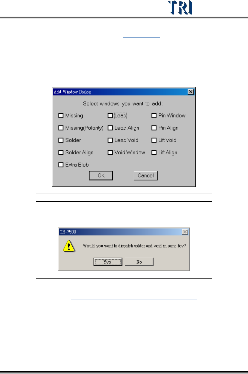
] to create multiple windows at the same time. Check the
windows that are needed. [Missing] and [Missing(Polarity)] are created on the [Body] box.
[Solder], [Lead], [Lead Void], [Pin Window] and [Lift Void] are created on the [Pin] boxes.
[Align] is created to cover all pins.
Figure 309: Add All Window Dialog
When selecting [Solder] and [Void Window] at the same time and pressing [OK], you can
select whether you want to arrange [Solder] and [Void] windows in the same FOV.
Figure 310: Confirm Window Arrangement in Same FOV
Example: Refer to Figure 311: Example -- Add All Windows Dialog. If we take the
upper leads of an IC, we can select the testing windows by the camera angles given
below.