TR7500_Series_Software_v29_En.pdf - 第150页
Test Research Inc. 128 TR7500 Series User Guid e –Softwa re v.2.9.0 5 E DIT C OMPO NENT D ATA The followi ng figure show s the main screen for editing componen t data. Figure 209 : Edit Componen t Data Main S creen The m…
Test Research Inc.
TR7500 Series User Guide –Software v.2.9.0 127
(4). [Translator List] – All translator lists in the system.
(5). [Import] – Load the new translator.
(6). [Quit] – Exit translator import program.
Test Research Inc.
128 TR7500 Series User Guide –Software v.2.9.0
5 E
DIT
C
OMPONENT
D
ATA
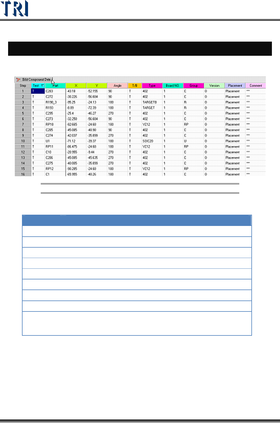
The following figure shows the main screen for editing component data.
Figure 209: Edit Component Data Main Screen
The meanings of the fields from left to right are:
NAME DESCRIPTION
Test
Test or do not test
Part
Component name
X
X coordinate
Y
Y coordinate
Angle
Component angle
T/B
Top or bottom side of the PCB
Type
Component type
Board NO.
Board number
Group
Group of the component. The system separates the group
automatically according to the beginning characters of the component.
The group can also be defined manually in the 7
th
field of the AOI file.
Test Research Inc.
TR7500 Series User Guide –Software v.2.9.0 129
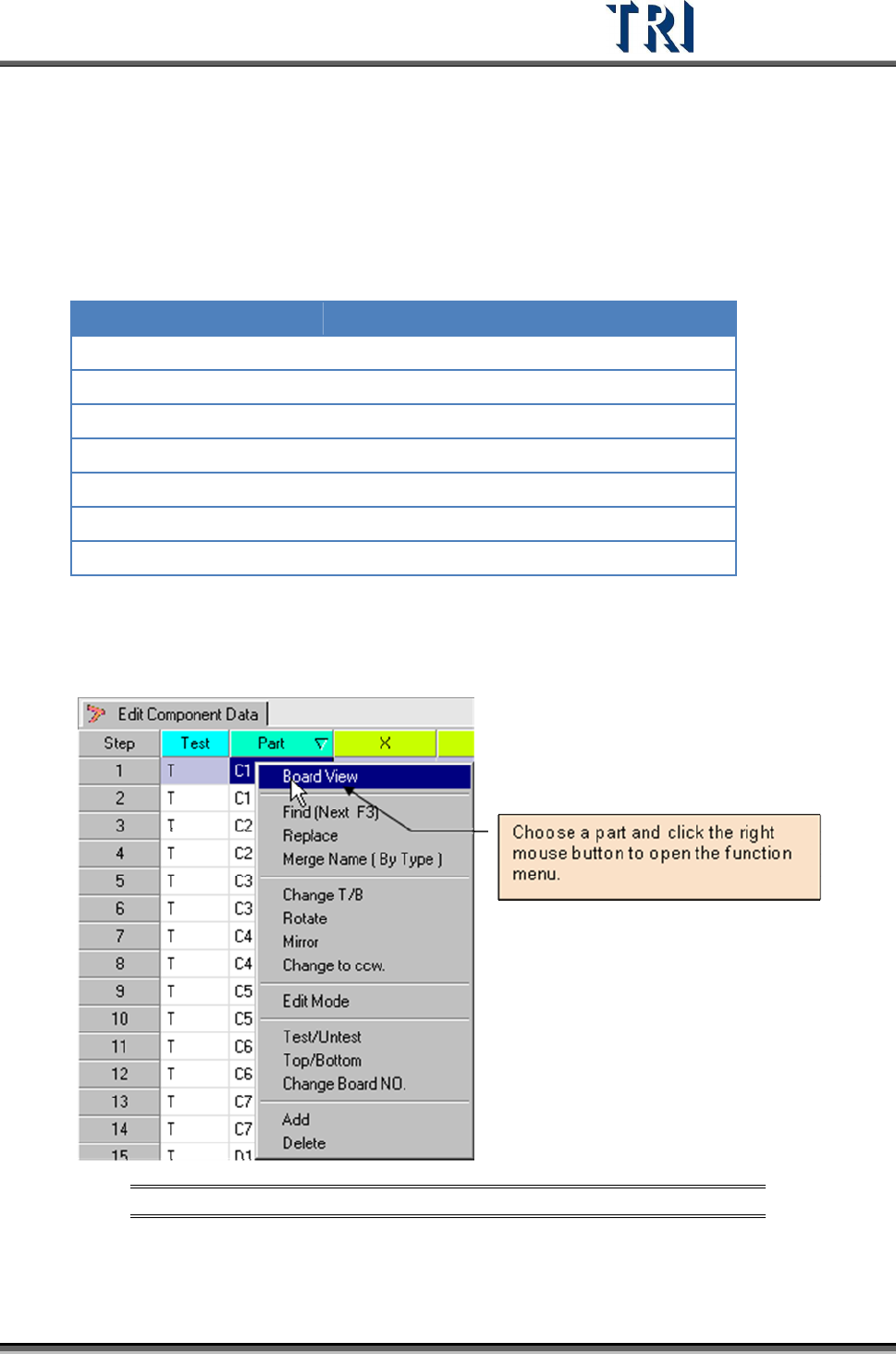
5.1 Overview
To edit component data, choose a component from the Edit Component Data window and
click the right mouse button. A menu will appear with a list of commands which will be
explained in this chapter.
Command Name Command Name
Board View Change to CCW. (CounterClockWise)
Find (Next F3) Edit Mode
Replace Test/Untest
Merge Name (By Type) Top/Bottom
Change T/B (Top/Bottom) Change Board No.
Rotate Add
Mirror Delete
5.2 Board View
Displays the component position on the board from the loaded AOI file.
Figure 210: Select Board View Command
After choosing this command, the Board View Window will be displayed, as shown in the
following figure.