TR7500_Series_Software_v29_En.pdf - 第60页
Test Research Inc. 38 TR7500 Series User Guide – Software v.2.9.0 2.11 FOV Verif y 1. Click the next button and go to next FOV veri f y process. Figure 66: FO V Verify Main Window 2. W hen the all processes are f inished…
Test Research Inc.
TR7500 Series User Guide –Software v.2.9.0 37
speed, but the arrangement of FOVs will be set as a panel. That is, the parameters
[By Set] cannot be applied in the project.
c. Review the Library of the component that is on the edge on an FOV. Try to reduce
the size of the inspection box and see if the problem will be solved.
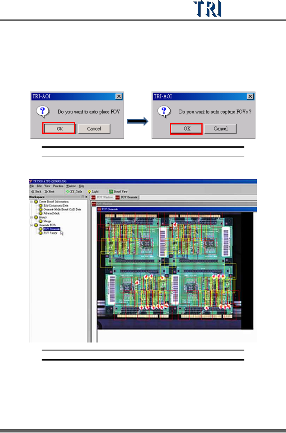
5. Warning message for auto place inspection FOV. Click [OK].
6. Auto-capture FOVs. Click [OK]. The panel FOV image will be created.
Figure 64: Confirm Auto-Place & Auto-Capture FOVs
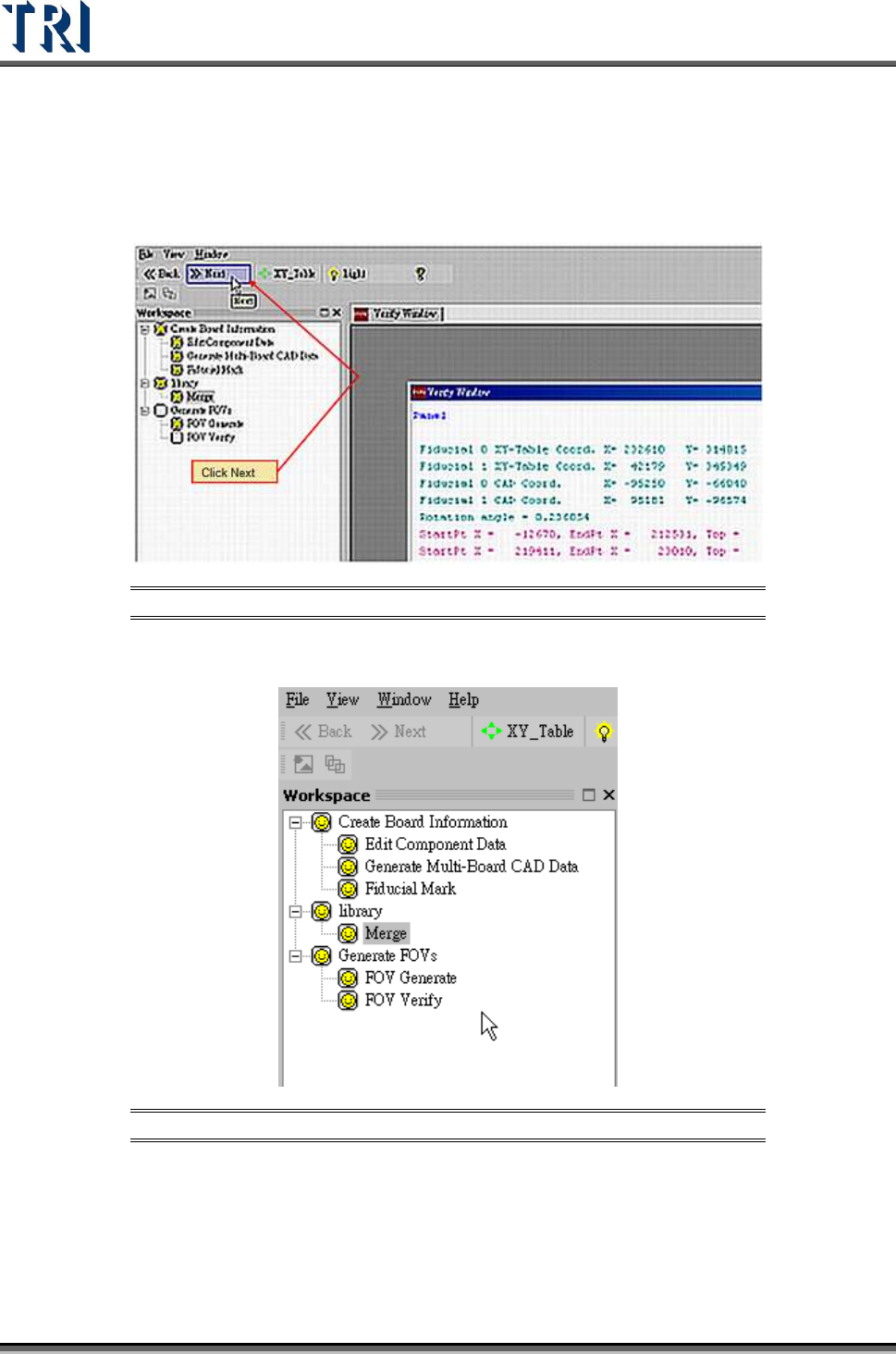
7. Display every FOV’s position in the panel.
Figure 65: Display All FOVs
8. Go to next step.
9. Confirm window close. Click [OK].
Test Research Inc.
38 TR7500 Series User Guide –Software v.2.9.0
2.11 FOV Verify
1. Click the next button and go to next FOV verify process.
Figure 66: FOV Verify Main Window
2. When the all processes are finished, close the window to go to the Train process.
Figure 67: Complete ATPG Process
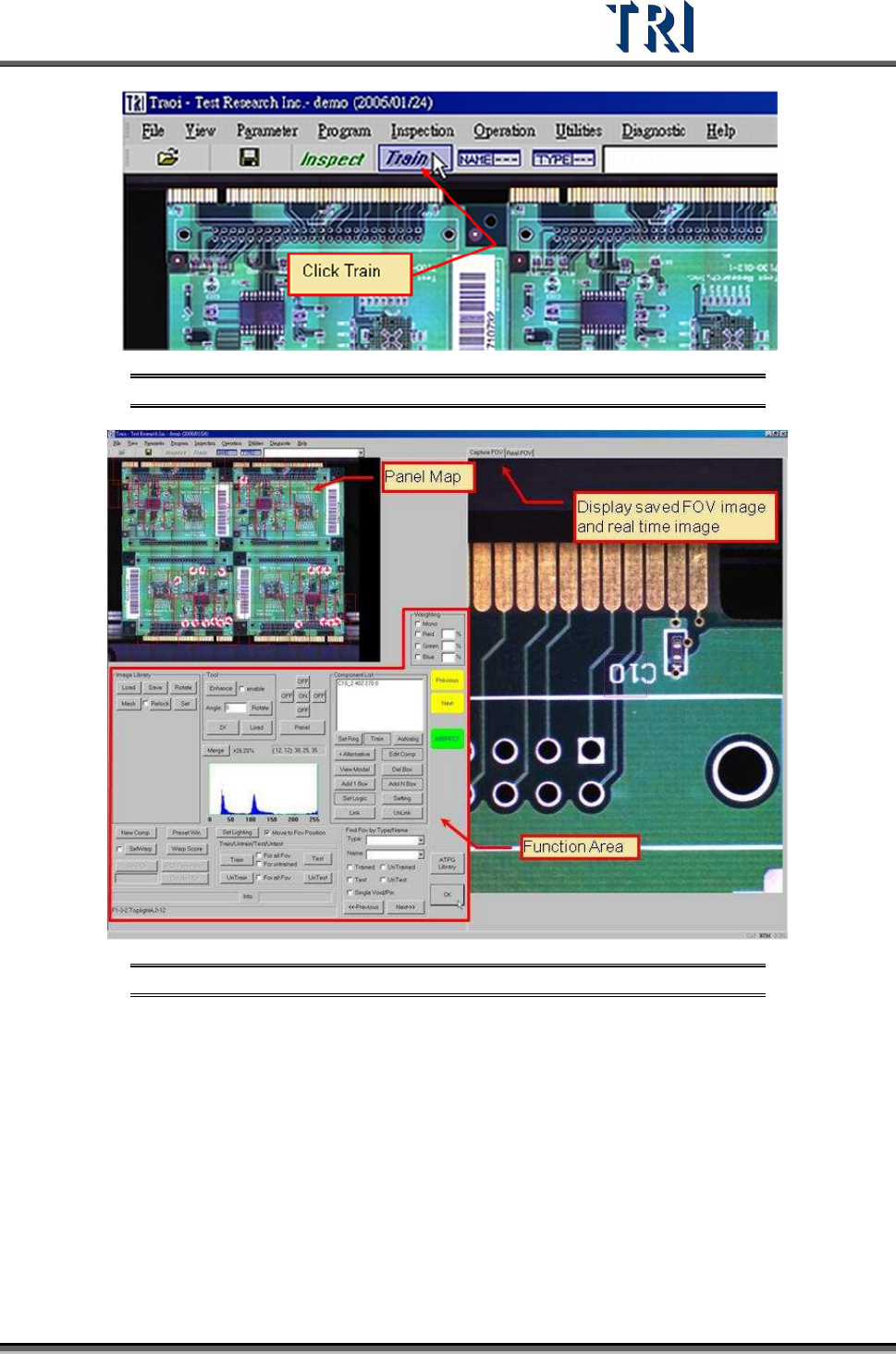
2.12 Train
1. Press [Train] to enter the Train dialog.
Test Research Inc.
TR7500 Series User Guide –Software v.2.9.0 39
Figure 68: Select Train Function
Figure 69: Train Function Main Window
2. Review the FOVs in sequence. Press [INSPECT] to check the result of inspection for
every inspection box.
3. Perform fine tuning if necessary. The most often used functions are:
a. Train inspection box
b. Add alternative image
c. Adjust the size and position of inspection box
d. Set the search
e. Set pass level
f. Change the lighting of FOV
g. Add or Delete FOV
h. Set Warp