TR7500_Series_Software_v29_En.pdf - 第252页
Test Research Inc. 230 TR7500 Series User Guid e –Softwa re v.2.9.0 Figure 384 : Pin Pass Level Settings [B/ W Threshold] – T he threshold to judge the black and w hite. [Hi g h Ratio] – Set the tolerance ratio tha t…
Test Research Inc.
TR7500 Series User Guide –Software v.2.9.0 229
9.2.4 Lead Void
Checks for no solder or open for IC leads. The algorithm is the same as for Void window.
The difference is not calculating the bright area as denominator when training the lead void.
The [Pass Level Settings] are shown in the following figure.
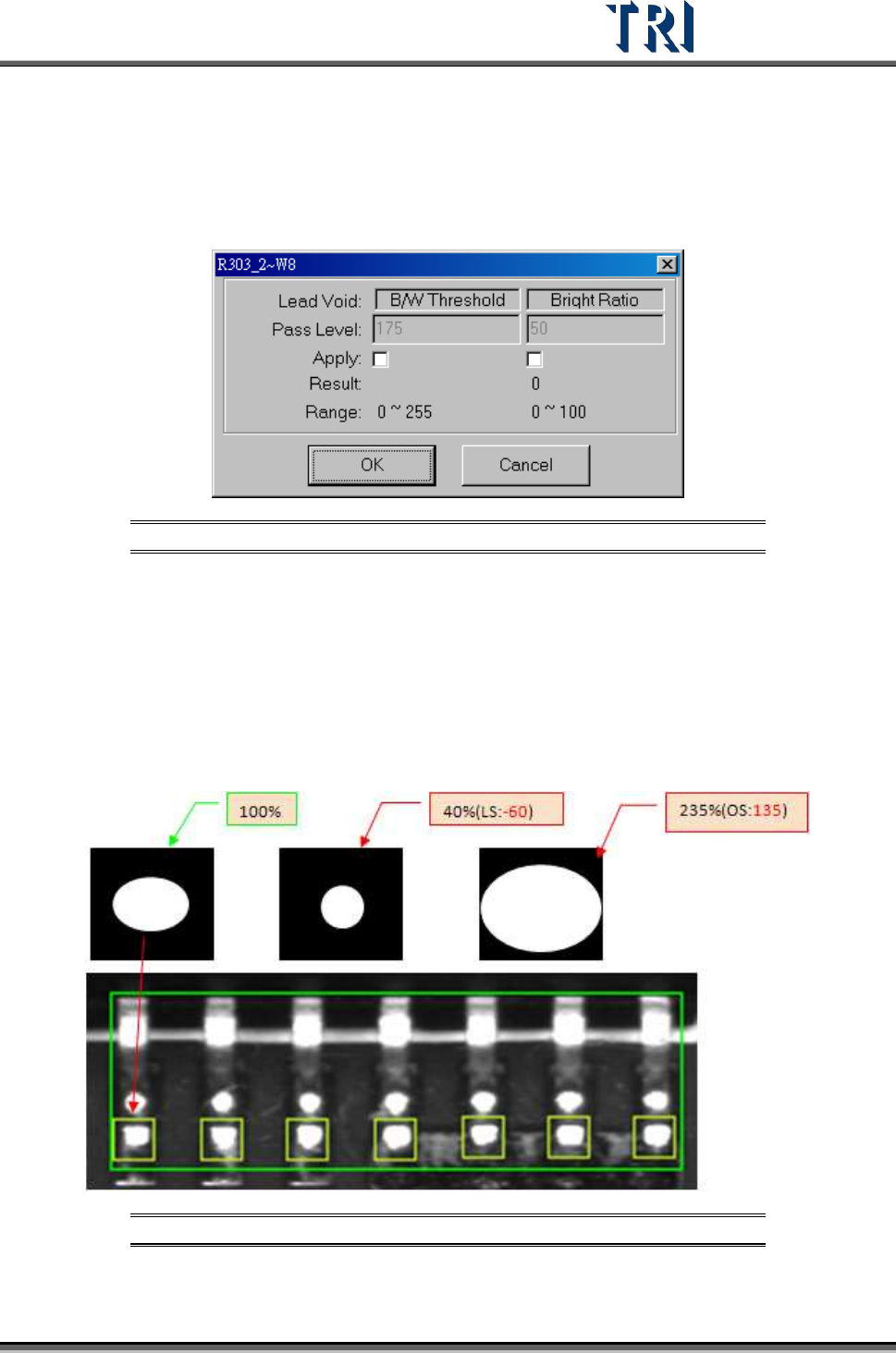
Figure 382: Lead Void Pass Level Settings
[B/W Threshold] – Set the threshold to judge the black and white.
[Bright Ratio] – Set the tolerance of white ratio.
9.2.5 Pin
Checks the shift, over/ low solder, or open of components. Set [Threshold} and {High/Low
Ratio] to check NG or not. When user trains a pin window, the software will memorize the
bright zone as 100.
Figure 383: 100% & Low Solder, Over Solder Settings
The [Pass Level Settings] are shown in the following figure.
Test Research Inc.
230 TR7500 Series User Guide –Software v.2.9.0
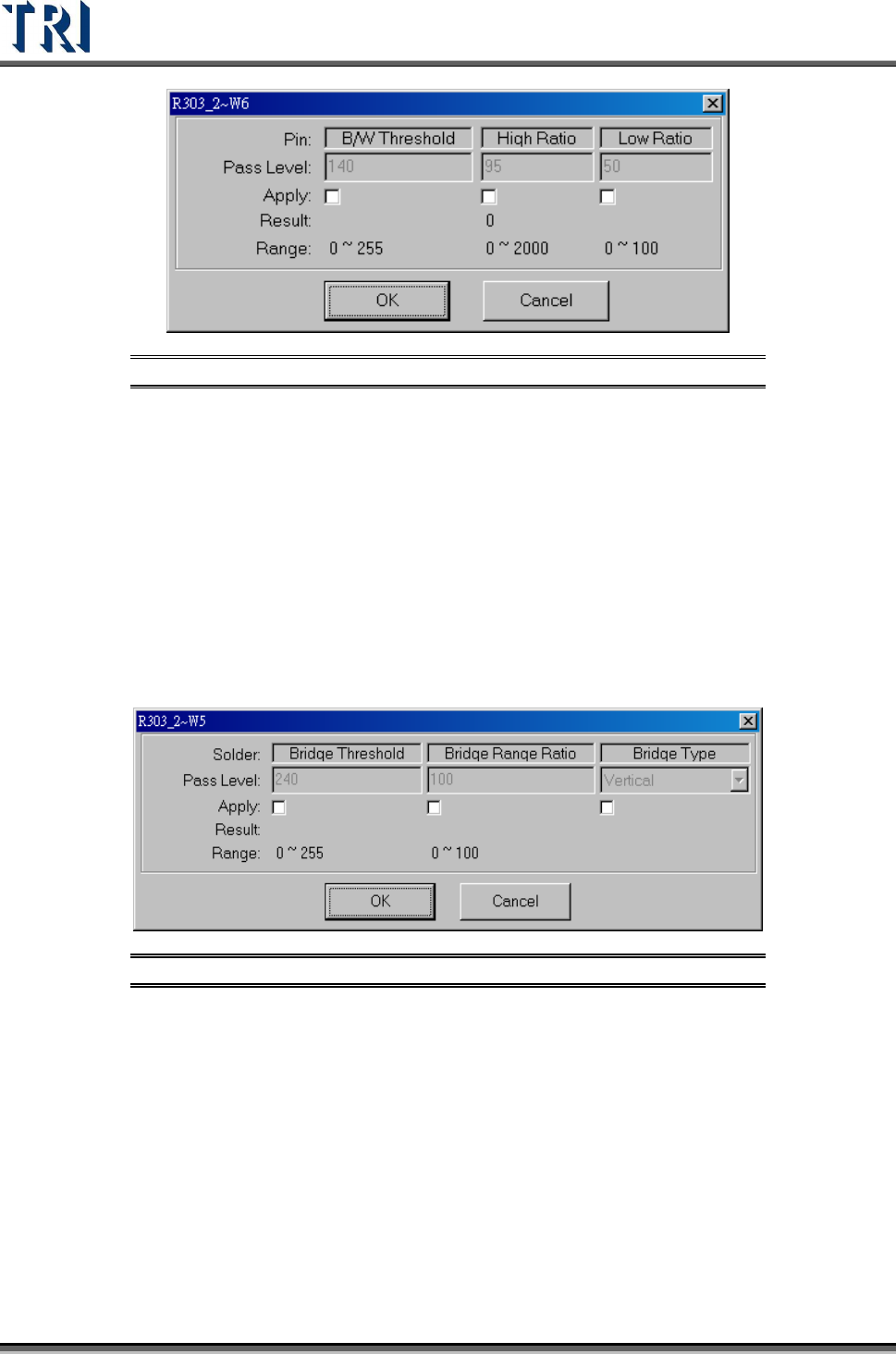
Figure 384: Pin Pass Level Settings
[B/W Threshold] – The threshold to judge the black and white.
[High Ratio] – Set the tolerance ratio that the box cannot exceed.
[Low Ratio] – Set the tolerance ratio that the box cannot be lower than.
9.2.6 Solder
Checks for bridging of IC leads. The [Solder] window is set with angle camera as default.
When the user trains the [Solder] window, the threshold will be automatically set according to
the surrounding area. Solder will be checked outward from the window. If the threshold is
exceeded by 7/10 pixels, it will show failure in standard/high resolution.The [Pass Level
Settings] are shown in the following figure.
Figure 385: Solder Pass Level Settings
[Bridge Threshold] – The threshold to judge the black and white.
[Bridge Range Ratio] – Set the percentage of pixels to inspect
[Bridge Type] – Set the direction to inspect.
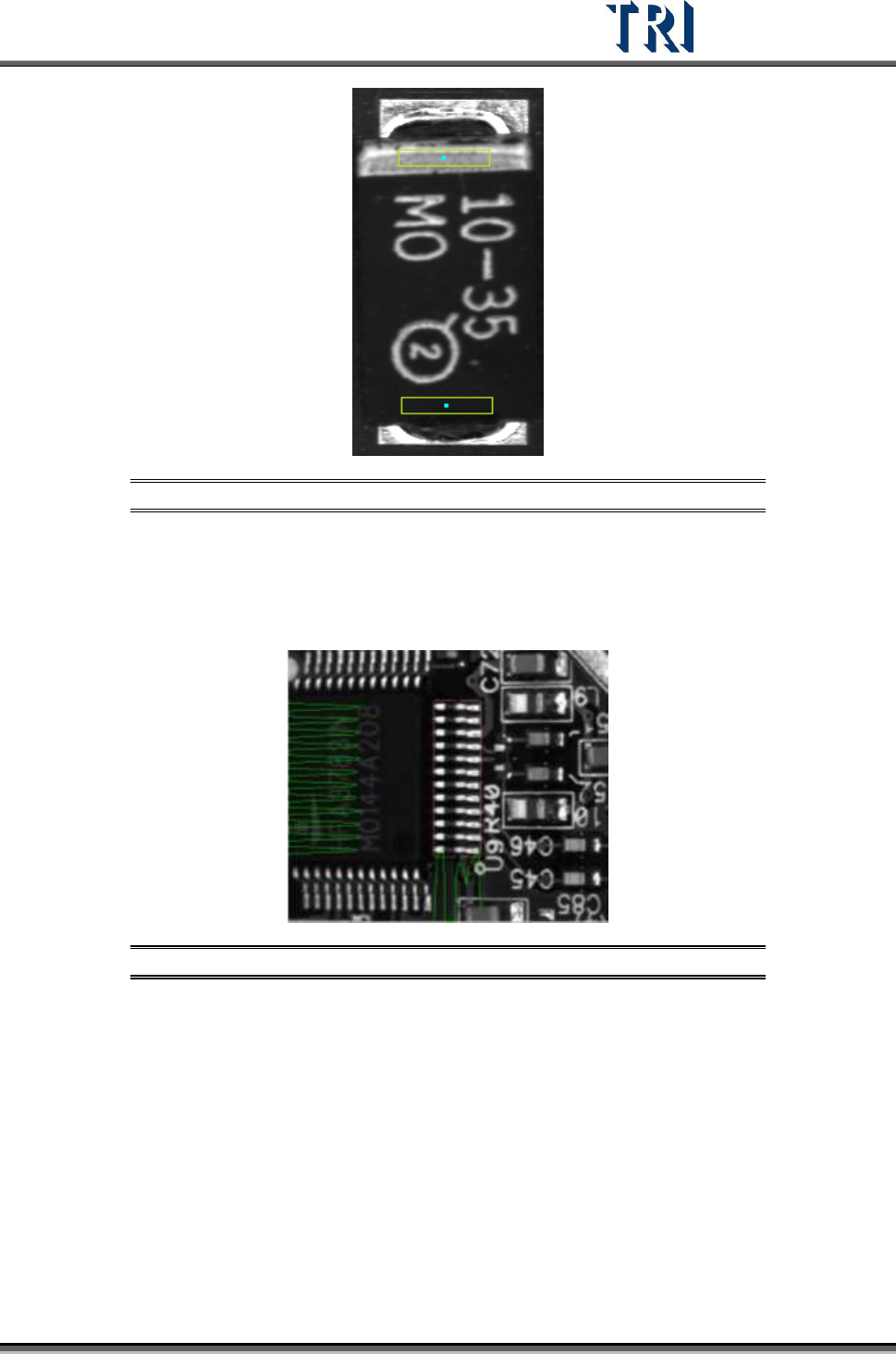
9.2.7 Polarity Pair
Move a pair of windows to different positions with a wide variation of gray level. System will
show polarity fail if the gray level of two windows is reversed.
Test Research Inc.
TR7500 Series User Guide –Software v.2.9.0 231
Figure 386: Set Two Polarity Pair Windows
9.2.8 Align
The [Align] window uses the projection in X-Y direction (Method3) to relocate an IC or Rnet
(Cnet) when the PCB is warped. Align only relocates one component.
Figure 387: Align Window
The [Pass Level Settings] are shown in the following figure.