2OM-1088-002.pdf - 第166页
Tg0699-PM-D2 0207-001 Chapter 1 4-19 3.1 "T ransfer Mode Set-up" T ab 3.1 "T ransfer Mode Set-up" T ab • • • • • Sheet Layout When the [T ransfer Mode Set-up] tab on the "DEVICE DA T A" wind…
Tg0699-PM-D2
0207-001 Chapter 1 4-18
3. "Device Data" Submenu
3. "Device Data" Submenu
••
••
• Window Layout
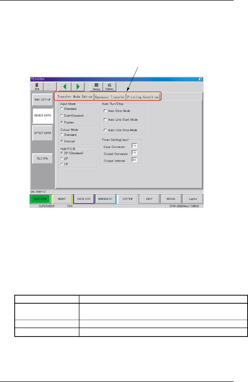
When the [DEVICE DATA] button is pressed in the "SYSTEM"
submenu bar, the following window appears.
Fig. 3D12 "DEVICE DATA" Window (Submenu)
••
••
• Window Composition
*1 Tabs
The "DEVICE DATA" window (submenu) is provided with 3 tabs.
Every time a tab is pressed, the corresponding tab sheet ap-
pears.
*1
Table 3D4
Tabs Description
Transfer Mode Set-up The corresponding tab sheet enables the operator to set
various data mainly for the in-line production.
Conveyor Transfer Set the various data items for the transfer conveyors.
Printing Condition Set the various data items for print mode.
Tg0699-PM-D2
0207-001 Chapter 1 4-19
3.1 "Transfer Mode Set-up" Tab
3.1 "Transfer Mode Set-up" Tab
••
••
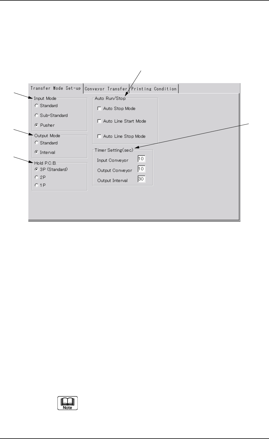
• Sheet Layout
When the [Transfer Mode Set-up] tab on the "DEVICE DATA"
window (submenu) is pressed, the following tab sheet appears.
Fig. 3D13 "Transfer Mode Set-up" Tab Sheet
••
••
• Sheet Composition
*1 Input Mode
Select one of the option buttons to determine the way how to
receive P.C.B.’s from the input machine.
Standard/Sub-Standard :
The machine receives the P.C.B.’s discharged
from the input machine.
The L conveyor is activated when a P.C.B.
transfer signal is received from the input
machine.
Pusher : The machine receives P.C.B.’s discharged
forcibly by the pusher from the input machine.
Turn on the desired option button. A dot appears inside
the circle, indicating that the desired item is selected.
*1
*2
*3
*4
*5

Tg0699-PM-D2
*2 Output Mode
It can be selected how to discharge P.C.B.’s to the output machine.
Standard : This machine turns on the P.C.B. transfer signal in re-
sponse to a P.C.B. requirement signal transmitted from
the output machine and keeps on discharging P.C.B.’s
until the P.C.B. requirement signal is turned off.
When the P.C.B. requirement signal is not turned off
within the specified time after this machine has started
discharging P.C.B.’s, the machine stops running in an
error condition.
Interval : This machine turns on a P.C.B. transfer signal in re-
sponse to a P.C.B. requirement signal transmitted from
the output machine and activates the conveyor to dis-
charge P.C.B.’s for the specified period of time.
*3 Hold P.C.B.
It can be determined whether or not P.C.B.'s should be retained on
the L conveyor, the table chute, and the R conveyor.
3P (Standard) : Three pieces of P.C.B.'s are retained on the
L conveyor, the table chute, and the R con-
veyor.
2P : Two pieces of P.C.B.'s are retained on the L
conveyor and the table chute.
1P : A P.C.B. is retained on the L conveyor. It is
printed and discharged when a P.C.B. re-
quirement signal from the output machine is
"ON".
(a) Select "2P" to prevent any foreign substances from
adhering to a printed P.C.B. on the R conveyor.
(b) When "1P" is selected, the P.C.B. on the R conveyor
is not transferred onto the table chute when a P.C.B.
requirement signal from the output machine is "OFF".
*4 Auto Run/Stop
It can be determined whether or not the machine should be started
or stopped automatically.
When you turn on the desired check box, a check mark (;) ap-
pears inside the box, indicating that the function is selected.
0207-001 Chapter 1 4-20
3.1 "Transfer Mode Set-up" Tab