2OM-1088-002.pdf - 第179页
Tg0699-PM-D2 0207-001 Chapter 1 4-31 4.1 "Machine Offset" T ab Screen Y Print Pos. : Input the of fset value of the screen Y- axis against the distance in Y direction on the table reference surface. *2 Conveyor…
Tg0699-PM-D2
0207-001 Chapter 1 4-30
4.1 "Machine Offset" Tab
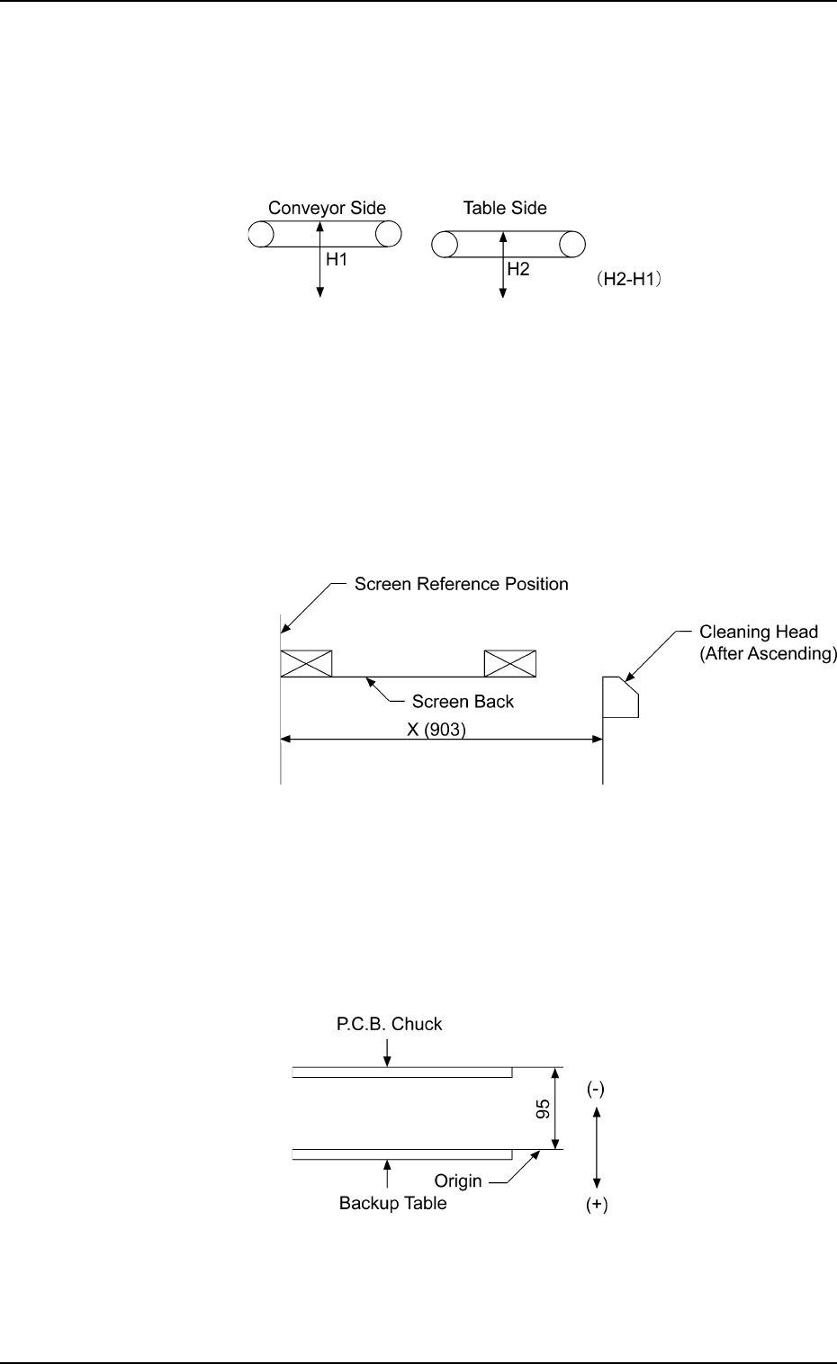
P.C.B. Transfer Height : Enter an offset value in the text
box, based on the specified distance
in the Z direction between the upper
surface of the table chute at its origin
and the lower surface of the P.C.B.
Fig. 3D23
Cleaning : Enter an offset value in the text box,
based on the specified distance in the
X direction between the cleaning head
at its cleaning position and the screen
center.
Fig. 3D24
P.C.B. Chuck Height : Enter an offset value in the text box,
based on the specified distance in the
Z direction between the P.C.B. backup
table at its origin and the lower surface
of the P.C.B.
Fig. 3D25

Tg0699-PM-D2
0207-001 Chapter 1 4-31
4.1 "Machine Offset" Tab
Screen Y Print Pos. : Input the offset value of the screen Y-
axis against the distance in Y direction
on the table reference surface.
*2 Conveyor Wd. Offset
Enter dimensions (widths) in the Y direction of the L/R convey-
ors and the table chute through which a P.C.B. passes. The
entered values are used to change the specified ones in the
pattern program.
L Conveyor Wd. : Enter an offset value (the dimension
representing the width through which
a P.C.B. on the L conveyor passes)
based on the specified one in the
pattern program.
R Conveyor Wd. : Enter an offset value (the dimension
representing the width through which
a P.C.B. on the R conveyor passes)
based on the specified one in the
pattern program.
Table Chute Wd. : Enter an offset value (the dimension
representing the width through which
a P.C.B. on the table chute passes)
based on the specified one in the
pattern program.
*3 Two-Camera Offset
Enter offset values in the text boxes based on the specified ones
for each axis, regarding the relative positional deviations be-
tween the P.E.C. and screen recognition cameras.
Fig. 3D26
When the 2-Camera Calibration operation is performed,
offset values can be entered automatically.
Center of P.E.C. Recognition Camera
Center of Screen Recognition Camera
X(+)
Y(+)
θ(+)
Tg0699-PM-D2
0207-001 Chapter 1 4-32
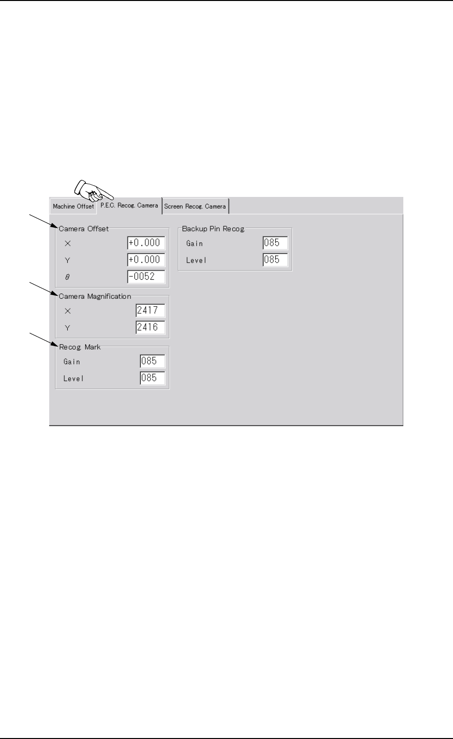
4.2 "P.E.C. Recog. Camera" Tab
4.2 "P.E.C. Recog. Camera" Tab
This tab sheet enables the operator to set offset values and magnifi-
cations of the P.E.C. recognition camera and gain & level (contrast
and brightness) of the fiducial mark.
••
••
• Sheet Layout
When the "P.E.C. Recog. Camera" tab is pressed in the "OFFSET
DATA" window (submenu), the following tab sheet appears.
Fig. 3D27 "P.E.C. Recog. Camera" Tab Sheet
*2
*3
*1