2OM-1088-002.pdf - 第69页
Tg0699-PM-D2 (7) PCB Cut Offset When the P .C.B. has a cutout at its edge and must be posi- tioned against the P .C.B. stopper , enter the depth of the cutout in the text box. Unit : mm 1.2.4 P .E.C. Recognition (1) P .E…
Tg0699-PM-D2
0207-001 Chapter 1 2-9
1.2 Operation Data
(4) Vacuum Rel. Wait Time
Set the waiting time during which the picked P.C.B. is released
and the backup table descends.
Unit : seconds
(5) PCB Clamp Offset
The backup table ascends to the position where a P.C.B. is
chucked.
It starts ascending again after the P.C.B. horizontal clamping
unit has chucked the P.C.B.
When thin P.C.B.’s are used and chuck errors occur, enter a
value as timing with which a P.C.B. is chucked and the backup
table starts ascending again and a value that represents the
position where the P.C.B. horizontal clamping unit starts to
chuck the P.C.B.
Timing [sec] : Enter a value that represents the
timing with which the backup starts
ascending again after it has stopped.
Unit : seconds
Position [mm] : Enter a value that represents the
changed dimension based on the
current position.
Unit : mm
When a minus (-) value is entered,
the height for chucking start can be
changed.
Bef.Clamp Bkup Spd. : The ascending speed of the backup
table can be set in the range of 10
steps (Full Speed to 90%Down)
before the P.C.B. is clamped.
Unit : %
Aft.Clamp Bkup Spd. : The ascending speed of the backup
table can be set in the range of 10
steps (Full Speed to 90%Down) after
the P.C.B. is clamped.
Unit : %
(6) P.C.B. Stopper Offset Y
Set the offset in the Y direction of the stopper that is used to
stop the P.C.B. in the table chute section.
Unit : mm
When the offset is "0" (zero), the P.C.B. stopper is located at
the center of the P.C.B. end plane.
Specify the offset when there is a cutout, etc., at the center of
the P.C.B. end plane.
Fig.3B26
Vacuum Rel. Wait Time
[sec]
0.0
Fig.3B27
Timing [sec]
Position [mm]
0.00
+0.0
Bef.Clamp
Bkup Spd.
Aft.Clamp
Bkup Spd.
Full Speed
Full Speed
P.C.B. Stopper Offset Y
[mm]
+000
Fig.3B28

Tg0699-PM-D2
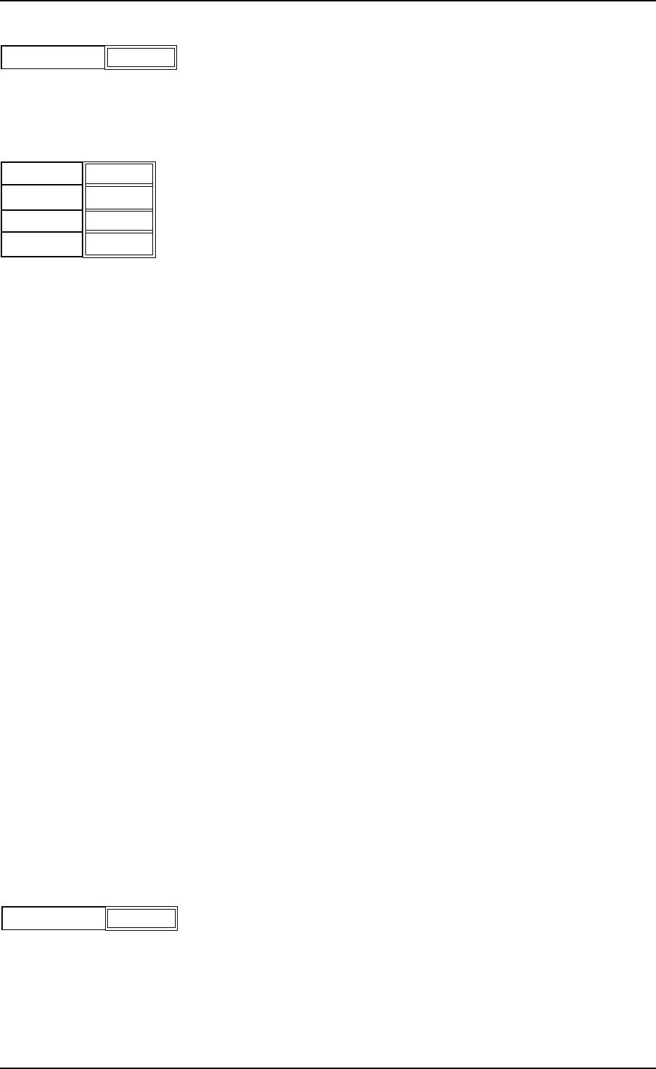
(7) PCB Cut Offset
When the P.C.B. has a cutout at its edge and must be posi-
tioned against the P.C.B. stopper, enter the depth of the cutout
in the text box.
Unit : mm
1.2.4 P.E.C. Recognition
(1) P.E.C. Recog. Function
Only "2-Point Recognition" is performed.
(2) Center Recognition
It can be selected whether or not the machine should perform
the center recognition.
ON : The machine performs the center recognition.
OFF : The machine does not perform the center recognition.
When the center recognition function is used, a fiducial mark is
recognized once and the camera is moved to the position
where the recognized fiducial mark is located at the center of
the visual field. After that, the fiducial mark is re-recognized.
The positional accuracy is improved because the mark is
recognized at the center of the visual field (the spot of the lens
with less distortion).
0207-001 Chapter 1 2-10
1.2 Operation Data
P.C.B. Cut Offset [mm]
000
Fig.3B29
PEC Recog. Function
2 PT.
Fig.3B30
Center Recognition
OFF
Fig.3B31

Tg0699-PM-D2
(3) Fiducial Mark #1
X [horizontal] and Y [vertical]
Set the coordinates of the first fiducial mark.
Unit : mm
Recog. Mode
Select the recognition mode.
Mark :
This recognition mode uses fiducial marks.
Model :
The image taken with the recognition camera is regis-
tered as "Model".
This mode uses the "Model" in place of fiducial marks.
Model + Mark :
This mode recognizes the image in the center of the
model as in the mark mode, after rough positioning with
the model mode.
Code
Set the code No. of the first fiducial mark.
Auto Gain Adj.
Select whether or not the automatic gain is adjusted when the
PEC recognition is tested.
ON : The automatic gain adjustment is performed.
OFF : No automatic gain adjustment is performed.
Gain, Level
This sets the amplification rate, when the signal of the image
(taken by the PCB recognition camera) is converted to image
data showing brightness.
• When the gain is decreased, the contrast becomes
greater.
• When the level is decreased, all of the brightness be-
comes greater.
Calib. Lamp
Normal : Selected when the contrast between fiducial mark
and PCB surface is adequate.
Ring : Selected when the gold-plated mark is used for
fiducial marks.
Both : Selected when the silver-plated mark is used on the
ceramic PCB and there is slight contrast between
the colour of the PCB surface and the fiducial
marks.
0207-001 Chapter 1 2-11
1.2 Operation Data
X (Horizontal)
Y (Vertical)
000.000
000.000
Recog. Mode
Mark
Fig.3B32
Code
01
Auto Gain Adj.
OFF
Gain
150
Level
150
Galib. Lamp
Normal