2OM-1088-002.pdf - 第437页
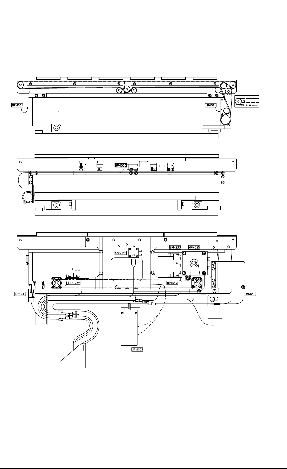
Tg0699-PM-D2 3.2 Location of Sensors and Loads in T able Section 0207-001 Chapter 3 3-38-7 T able 5C3 Symbols Name BPH050 P .C.B. Horizontal Clamping Forward Limit BPH051 Width Error Detection (Light Emitting Side) B051 …
Tg0699-PM-D2
3.2 Location of Sensors and Loads in Table Section
0207-001-(M782YE---0001) Chapter 3 3-38-6
Width Error
Detection
P.C.B. Horizonal Clamping Forward End
Table Width Axis Motor
Origin
Vacuum
Switch
Width
Origin
Cable Bearer
P.C.B. U/D Axis Pulse Motor
Table Conveyor Moto
r

Tg0699-PM-D2
3.2 Location of Sensors and Loads in Table Section
0207-001 Chapter 3 3-38-7
Table 5C3
Symbols Name
BPH050 P.C.B. Horizontal Clamping Forward Limit
BPH051 Width Error Detection (Light Emitting Side)
B051 Width Error Detection (Light Receiving Side)
SVS052 Vacuum Switch
BPH053 Table Z-Axis Interlock
BPH054 Table Z-Axis Correction Position
BPH171 Table Z-Axis Origin
BPH172 Table Z-Axis Limit (+)
BPH173 Table Z-Axis Limit (-)
BPH191 Table X-Axis Origin
BPH192 Table X-Axis Limit (+)
BPH193 Table X-Axis Limit (-)
BPH194 Table X-Axis Rotational Origin
BPH211 Table θ -Axis Origin
BPH212 Table θ -Axis Limit (+)
BPH213 Table θ -Axis Limit (-)
BPH214 Table θ -Axis Rotational Origin
BPH231 P.C.B. U/D Axis Origin
BPH232 P.C.B. U/D Axis Limit (+)
BPH233 P.C.B. U/D Axis Limit (-)
BPH251 Rail Axis Origin
MSMD017 Table Z-Axis Servomotor
MPM019 Table X-Axis Pulse Motor
MPM021 Table θ -Axis Pulse Motor
Tg0699-PM-D2
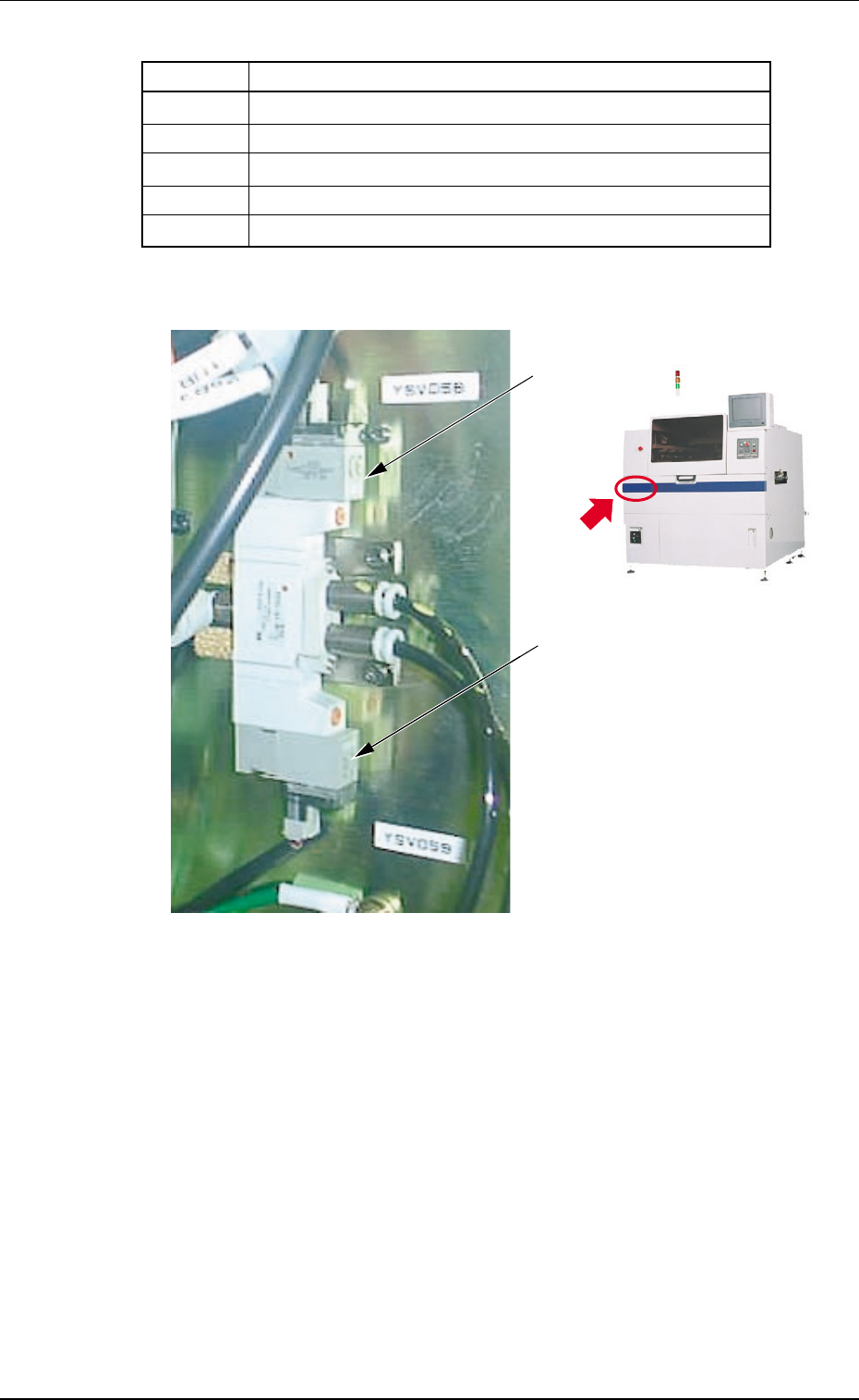
YSV058
YSV059
3.2 Location of Sensors and Loads in Table Section
0304-002 Chapter 3 3-38-8
Table 5C4
Symbols Name
MPM023 P.C.B. U/D Pulse Motor
MPM025 Pulse Motor for Rail Width Change
M004 Table Conveyor Motor
YSV058 P.C.B. Horizontal Clamping Solenoid Valve (Outward)
YSV059 P.C.B. Horizontal Clamping Solenoid Valve (Backward)
Fig. 5C5Fig. 5C5
Fig. 5C5Fig. 5C5
Fig. 5C5