2OM-1088-002.pdf - 第397页
Tg0699-PM-D2 Pneumatic Diagram (Details D) 0207-001-(M782XA---0002) Chapter 3 3-6 Pneumatic Diagram (Details D) 33 37 40 41 5 2 48 49 5 -1 6 6 -1 6 -2 7 7 - 1 7 - 2 5 1 10 18 21 22 23 24 X 2 28 29 Loc k C leanin g Sectio…
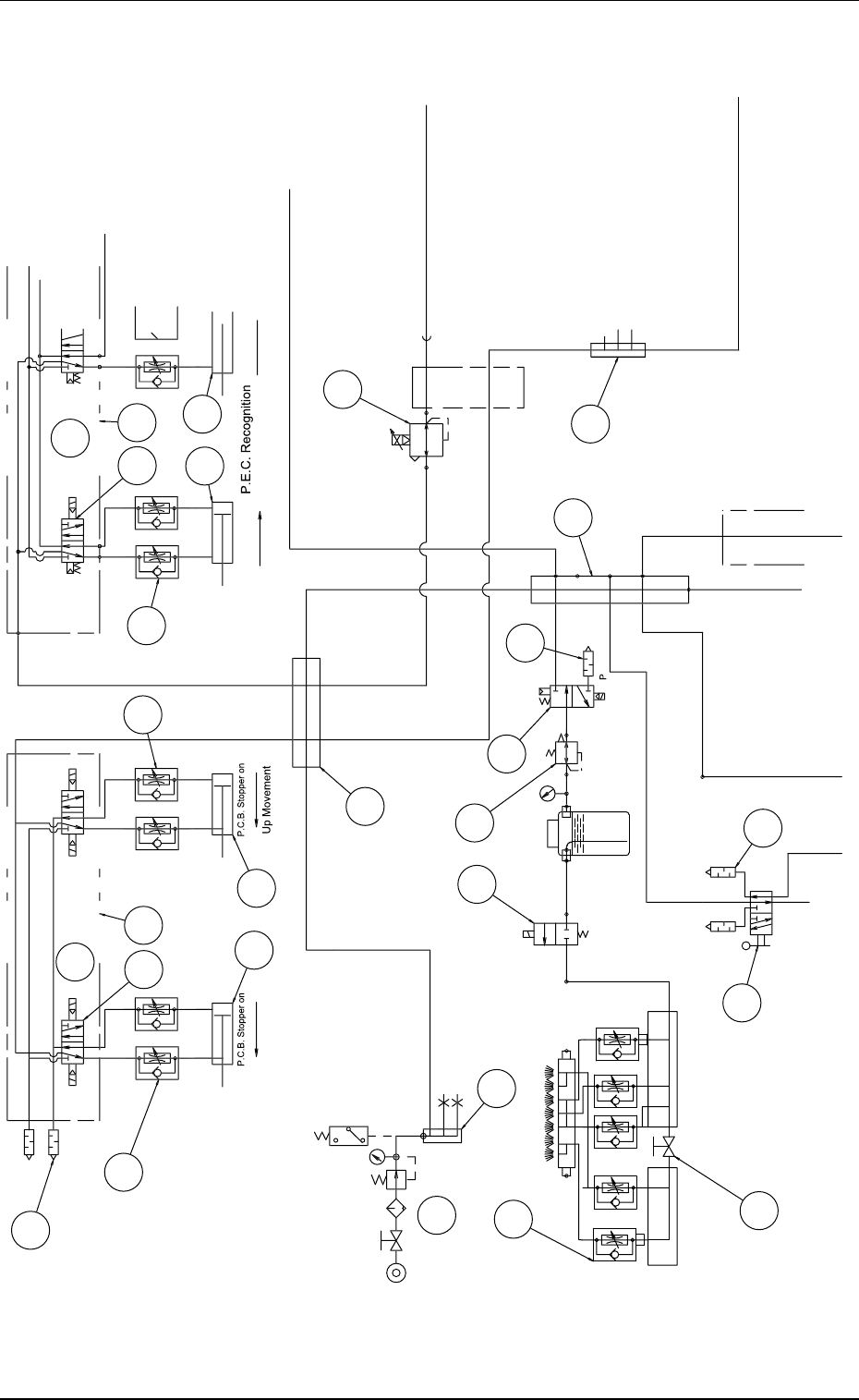
Tg0699-PM-D2
Pneumatic Diagram (Details C)
0207-001-(M782XA---0002) Chapter 3 3-5
Pneumatic Diagram (Details C)
3
2
3
4
37
4
1
5
2
35
Do
wn M
o
v
e
m
e
nt
R Conve
y
or Section
φ
4
φ
4
φ
6
C
onve
y
or
A
B
YS
V
0
4B
41
4
2
45
46
46
47
1
-1
1
-
2
1
2
-
1
2
-2
2
YS
V-
0
4E
YS
V-
0
4F
8
9
10
1
1
1
2
13
14
25
25
25
Se
rvi
ce
Air
C
reanin
g
Air Blower
(
Option
)
Ma
in M
ac
hin
e
Up
movement
Up
Movement
C
leanin
g
Section
L
Conve
y
or Section
S
ection
φ
6
φ
6
φ
8
φ
1
0
φ
4
φ
4
φ
6
φ
4
φ
4
φ
4
φ
4
φ
4
YS
V
08A
YS
V
098
YS
V
0
7
9
YS
V
0
4A
Cab
l
e
B
ea
r
e
r
φ
6
φ
6
φ
6
φ
1
0
φ
1
0
φ
6
φ
6
C
onve
y
or
A
B
P
.C.B. Holdin
g
P
.C.B. Sto
pp
er
P
T1
/8
P
A
B
B
A
A
φ
6
EXH
SU
P
φ
6
φ
6
S
ettin
g
0.34 MPa
(
3.5 k
g
f/cm
2
)
S
ettin
g
0.39 MPa
(
4 k
g
f/cm
2
)
0
.
39
MP
a
o
r m
o
r
e
(
4 k
g
f/cm
2
)
OUT
O
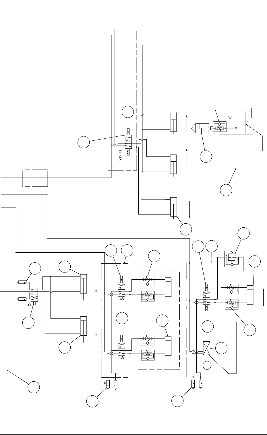
Tg0699-PM-D2
Pneumatic Diagram (Details D)
0207-001-(M782XA---0002) Chapter 3 3-6
Pneumatic Diagram (Details D)
33
37
40
41
5
2
48
49
5
-1
6
6
-1
6
-2
7
7
-
1
7
-
2
5
1
10
18
21
22
23
24
X
2
28
29
Loc
k
C
leanin
g
Section
50
Duct
D
ir
ec
ti
o
n
o
f Exh
aus
t
D
ir
ec
ti
o
n
o
f Exh
aus
t
Lock
V
acuum Section
C
leanin
g
Section
S
creen Holder
S
ection
Vacuu
m Chan
g
eover Unit
φ
8
φ
1
0
φ
4
φ
4
φ
6
φ
6
φ
6
φ
6
φ
6
φ
6
43
YS
V
089
YS
V
088
YS
V
099
YS
V
098
YS
V11A
Cab
l
e
B
ea
r
e
r
C
h
uc
k
Suc
ti
o
n
C
leanin
g
Suction
A
B
B
A
P
R2
B
A
R2
R1
P
C
leanin
g
Unit Clampin
g
(
Ri
g
ht
)
Lock
C
leanin
g
Unit Clampin
g
(
Left
)
φ
6
Do
wnw
a
r
d
M
o
v
e
m
e
nt
C
leanin
g
Up/Down
(
Front
)
P
A
B
P
os
i
t
i
on
i
n
g
S
creen To
p
Holder
(
Left Side
)
Loc
k
S
creen To
p
Holder
(
Left Side
)
C
leanin
g
Air Blower
(
Option
)
S
creen Frame Positionin
g
(
Vertical
)
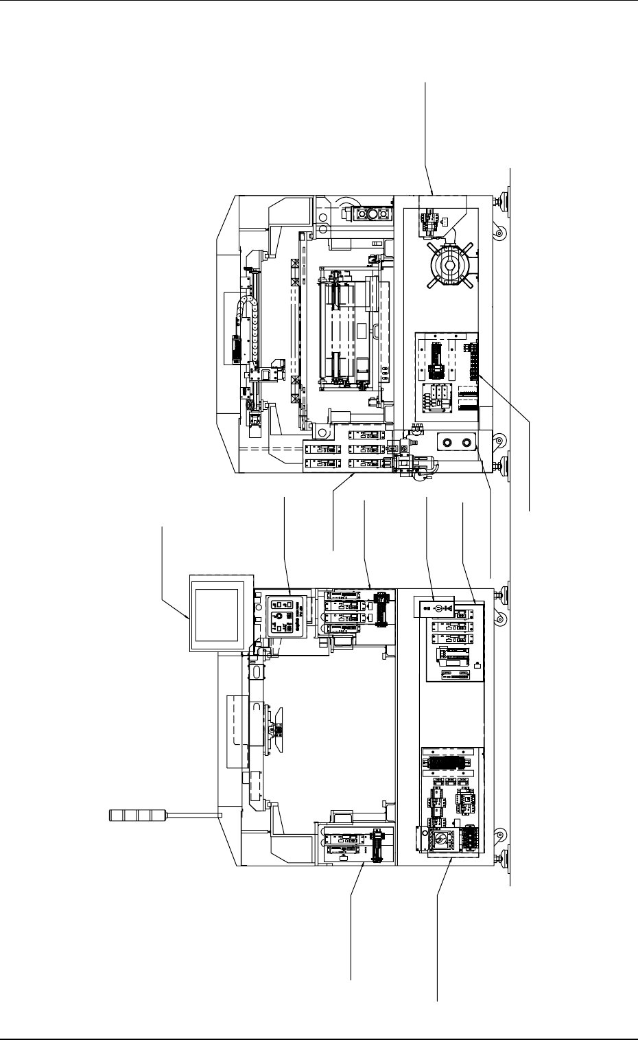
Tg0699-PM-D2
2. Parts Location
General View 1
2. Parts Location
0207-001-(M782YA---0001) Chapter 3 3-7
Control Box Section
P.C.B. Chuck Section
Main Power Supply Section
(Front View) (Rear View)
Operation Panel
Section
Driver 2 Section
P.C.B. Transfer
Section
Console Section
Driver 1 Section
Front and Rear Interface
Section
Relay Sequence Section
Vacuum Pump Section