2OM-1088-002.pdf - 第439页
Tg0699-PM-D2 3.3 Location of Sensors and Loads for P .E.C. Recognition Section 0207-001-(M782YG---0001) Chapter 3 3-38-9 3.3 Location of Sensors and Loads for P .E.C. Rec- ognition Section Origin P.E.C. Recognition Y-Axi…
Tg0699-PM-D2
YSV058
YSV059
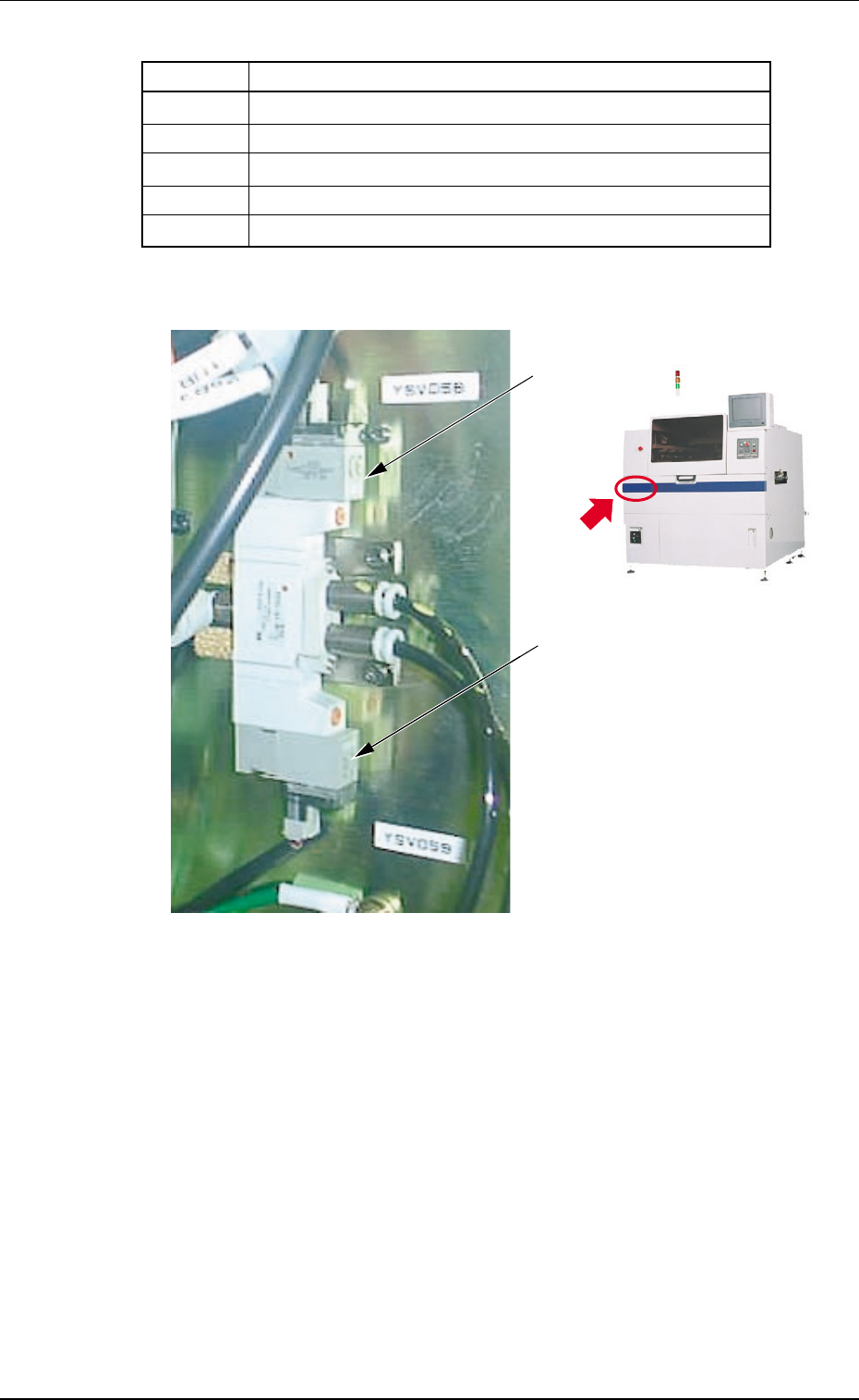
3.2 Location of Sensors and Loads in Table Section
0304-002 Chapter 3 3-38-8
Table 5C4
Symbols Name
MPM023 P.C.B. U/D Pulse Motor
MPM025 Pulse Motor for Rail Width Change
M004 Table Conveyor Motor
YSV058 P.C.B. Horizontal Clamping Solenoid Valve (Outward)
YSV059 P.C.B. Horizontal Clamping Solenoid Valve (Backward)
Fig. 5C5Fig. 5C5
Fig. 5C5Fig. 5C5
Fig. 5C5
Tg0699-PM-D2
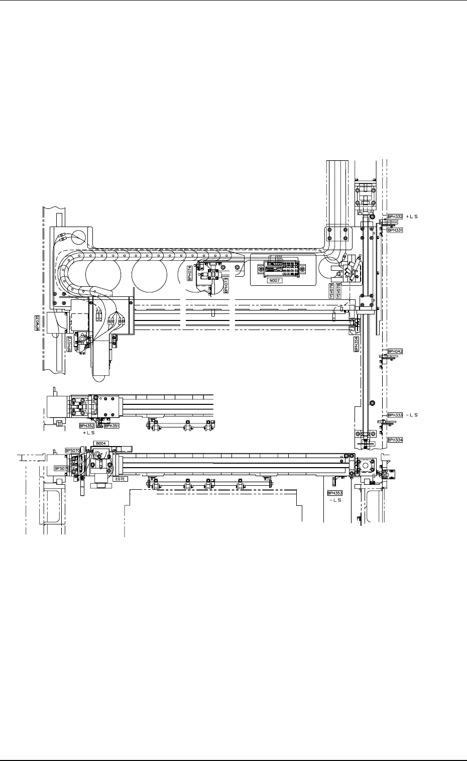
3.3 Location of Sensors and Loads for P.E.C. Recognition Section
0207-001-(M782YG---0001) Chapter 3 3-38-9
3.3 Location of Sensors and Loads for P.E.C. Rec-
ognition Section
Origin
P.E.C. Recognition Y-Axis I. L.
Rotational Origin
Rotational Origin
Origin
P.E.C. Recognition Camera
P.C.B. Stopper Upper Limit
P.E.C. Recognition
P.E.C. Recognition X-Axis Pulse Motor
P.C.B. Stopper Lower Limit
Lighting for
P.E.C. Recognition
Overlapped P.C.B. Detection
P.C.B. Warpage Holding Output Side
Tg0699-PM-D2
3.3 Location of Sensors and Loads for P.E.C. Recognition Section
0207-001 Chapter 3 3-38-10
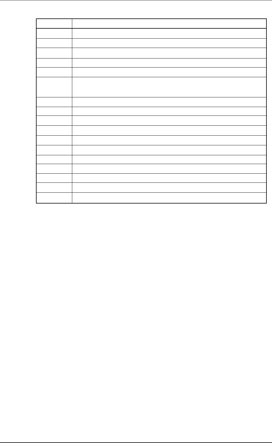
Table 5C5
Symbols Name
BPH042 P.E.C. Recognition Y-Axis Interlock
BPS070 P.C.B. Stopper Upper Limit
BPS071 P.C.B. Stopper Lower Limit
BPH072 P.C.B. Check
BPH073 P.C.B. Warpage Top Holding Output Side
BPH074 P.C.B. Warpage Top Holding Input Side
(Overlapped P.C.B. Detection)
BPH331 P.E.C. Recognition Y-Axis Origin
BPH332 P.E.C. Recognition Y-Axis Limit (+)
BPH333 P.E.C. Recognition Y-Axis Limit (-)
BPH334 P.E.C. Recognition Y-Axis Rotational Origin
BPH351 P.E.C. Recognition X-Axis Origin
BPH352 P.E.C. Recognition X-Axis Limit (+)
BPH353 P.E.C. Recognition X-Axis Limit (-)
BPH354 P.E.C. Recognition X-Axis Rotational Origin
MPM035 P.E.C. Recognition X-Axis Pulse Motor
YSV078 P.C.B. Warpage Top Holding Upper Limit Solenoid Valve
YSV079 P.C.B. Stopper Solenoid Valve