2OM-1088-002.pdf - 第456页
0207-001 Chapter 3 3-42 Tg0699-PM-D2 4.1 Electrical and Electronic Symbols Name Symbol Graphic Symbols Remarks Relay K* Coil Contact a Contact b Contact c T iming Relay KT* Coil (ON Delay) (ON Delay) Contact a (Make Poin…
0207-001 Chapter 3 3-41 Tg0699-PM-D2
4.1 Electrical and Electronic Symbols
Name Symbol Graphic Symbols Remarks
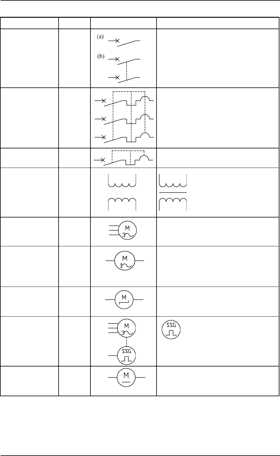
Air-Break Switch
Breaker Q*
Circuit Breaker Q*
Circuit Protector
Transformer T* Transformers with iron
cores are used in the
machine and are expressed
as shown in the left figure.
Three-Phase M*
Alternating
Current Motor
Single-Phase M*
Alternating
Current Motor
Cooling Fan MFAN*
Stepping Motor MPM*
Servomotor MSVM* The left figure shows an en-
coder.
DC Motor
0207-001 Chapter 3 3-42 Tg0699-PM-D2
4.1 Electrical and Electronic Symbols
Name Symbol Graphic Symbols Remarks
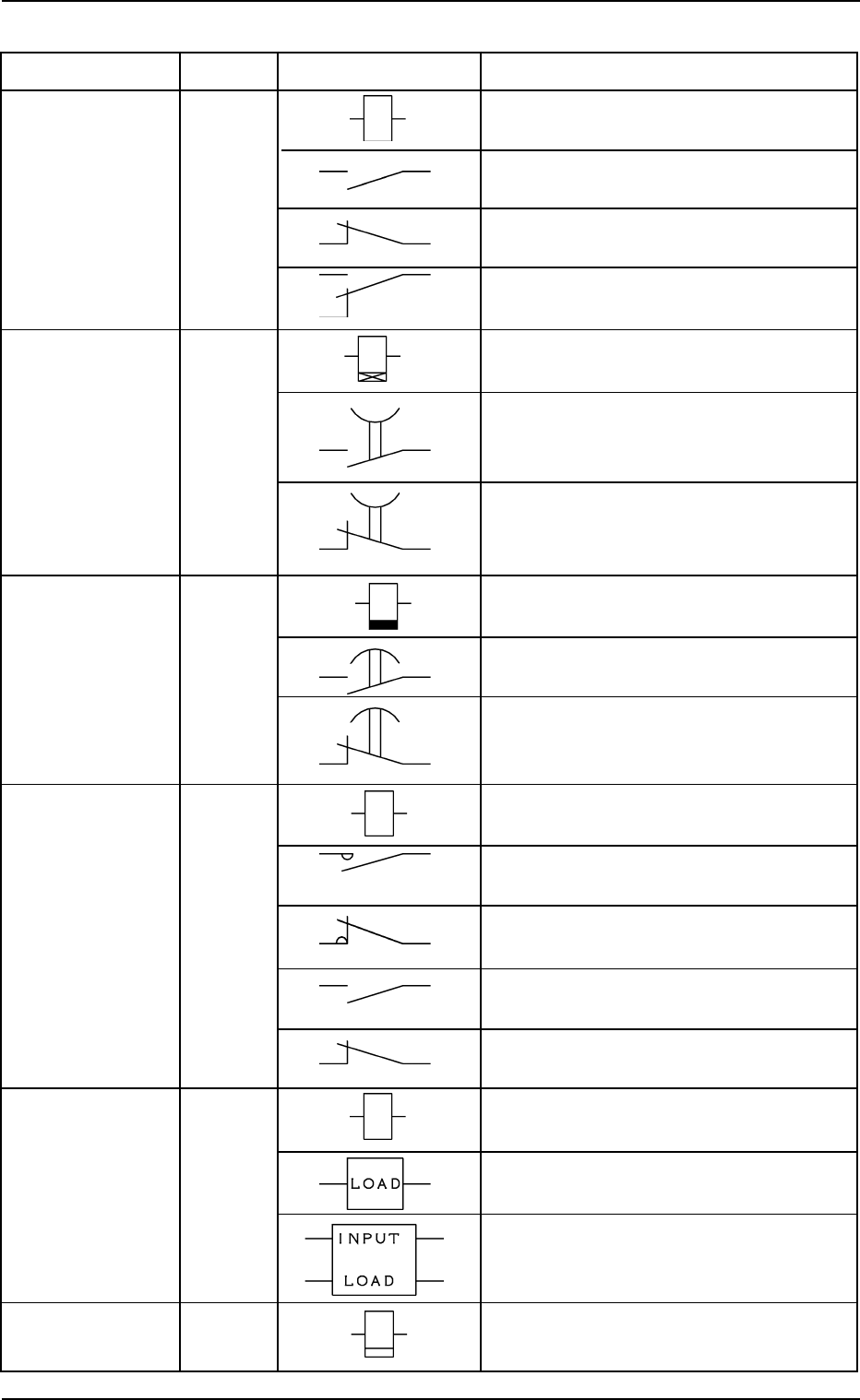
Relay K* Coil
Contact a
Contact b
Contact c
Timing Relay KT* Coil
(ON Delay) (ON Delay)
Contact a
(Make Point)
Timer
Contact b
(Break Point)
Timing Relay KT* Coil
(OFF Delay) (ON Delay)
Contact a
(Make Point)
Contact b
(Break Point)
Electromagnetic KM* Coil
Contactor
Main Contact a
Main Contact b
Sub Contact a
Sub Contact b
Solid-State Relay KSSR* INPUT
LOAD
A relay may be drawn using both “INPUT
and “LOAD”.
Cycle Counter
4.1 Electrical and Electronic Symbols
Name Symbol Graphic Symbols Remarks
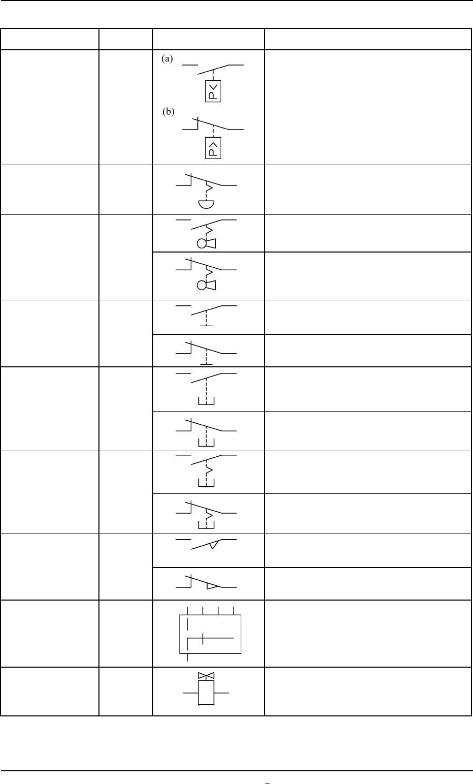
Pressure Switch SP*
Emergency Stop SPB*
Switch
Key Switch S* Contact a
Contact b
Toggle Switch S* Contact a
Contact b
Pushbutton SPB* Contact a
Switch
(Momentary)
Contact b
Pushbutton SPB* Contact a
Switch
(Alternate)
Contact b
Safety Door SQ* Contact a
Switch
Limit Switch Contact b
Selector Switch S* The theory of contact combination is de-
scribed near the graphic symbols.
Solenoid Valve YSV*
0207-001 Chapter 3 3-43 Tg0699-PM-D2