2OM-1088-002.pdf - 第457页
4.1 Electrical and Electronic Symbols Name Symbol Graphic Symbols Remarks Pressure Switch SP* Emergency Stop SPB* Switch Key Switch S* Contact a Contact b T oggle Switch S* Contact a Contact b Pushbutton SPB* Contact a S…
0207-001 Chapter 3 3-42 Tg0699-PM-D2
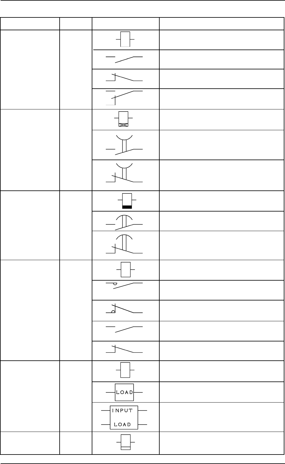
4.1 Electrical and Electronic Symbols
Name Symbol Graphic Symbols Remarks
Relay K* Coil
Contact a
Contact b
Contact c
Timing Relay KT* Coil
(ON Delay) (ON Delay)
Contact a
(Make Point)
Timer
Contact b
(Break Point)
Timing Relay KT* Coil
(OFF Delay) (ON Delay)
Contact a
(Make Point)
Contact b
(Break Point)
Electromagnetic KM* Coil
Contactor
Main Contact a
Main Contact b
Sub Contact a
Sub Contact b
Solid-State Relay KSSR* INPUT
LOAD
A relay may be drawn using both “INPUT
and “LOAD”.
Cycle Counter
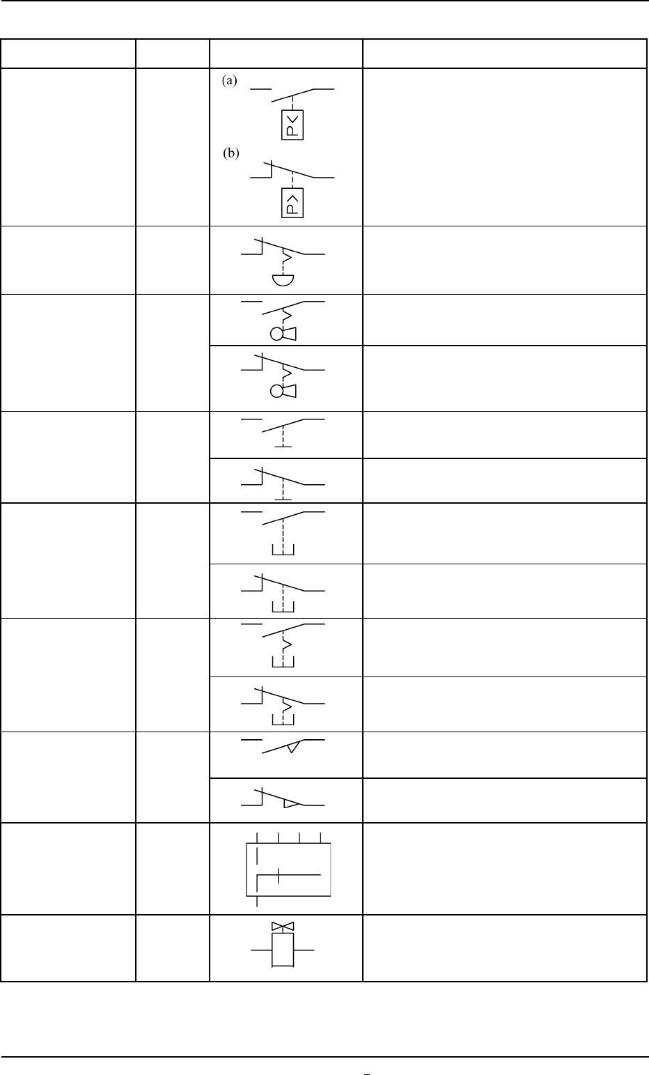
4.1 Electrical and Electronic Symbols
Name Symbol Graphic Symbols Remarks
Pressure Switch SP*
Emergency Stop SPB*
Switch
Key Switch S* Contact a
Contact b
Toggle Switch S* Contact a
Contact b
Pushbutton SPB* Contact a
Switch
(Momentary)
Contact b
Pushbutton SPB* Contact a
Switch
(Alternate)
Contact b
Safety Door SQ* Contact a
Switch
Limit Switch Contact b
Selector Switch S* The theory of contact combination is de-
scribed near the graphic symbols.
Solenoid Valve YSV*
0207-001 Chapter 3 3-43 Tg0699-PM-D2
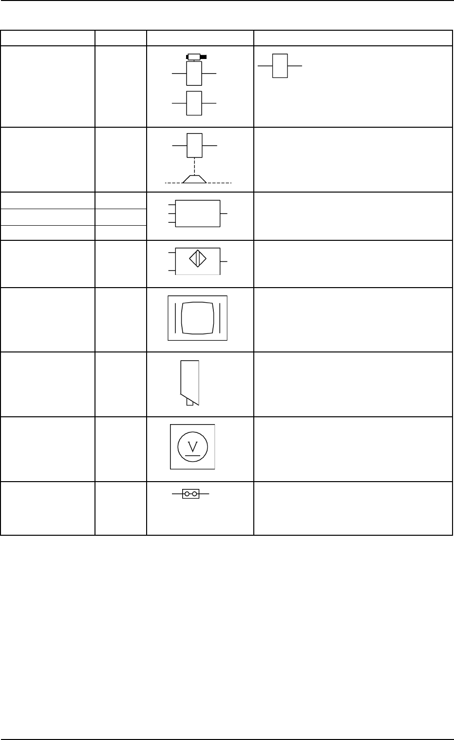
4.1 Electrical and Electronic Symbols
Name Symbol Graphic Symbols Remarks
Solenoid YSOL* The solenoid in the left figure
is used for the electromag-
netic lock-type door switches.
Electromagnetic
Brake
(OFF Brake)
Photosensor BPH*
Position Switch BPS*
Vacuum Sensor SVS*
Proximity Sensor BPX*
Monitor Display
Touch Screen
Camera CAM*
Voltmeter P*
Jumper The left figure represents a
jumper socket (jumper mount-
ing) in a unit P.C.B.
0207-001 Chapter 3 3-43-1 Tg0699-PM-D2