2OM-1088-002.pdf - 第455页
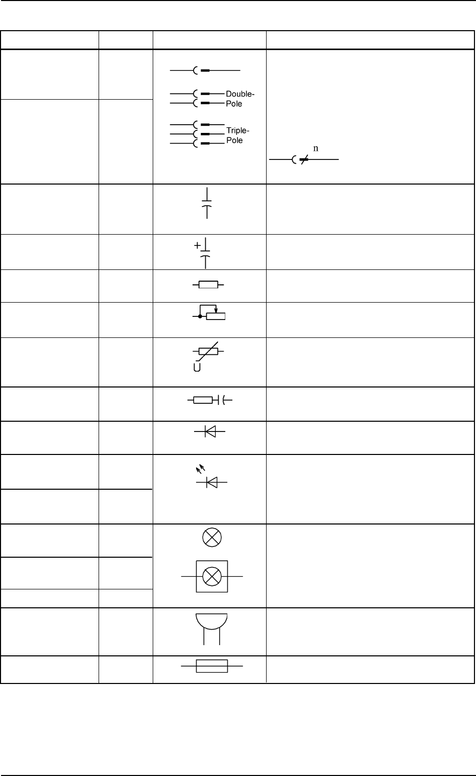
0207-001 Chapter 3 3-41 Tg0699-PM-D2 4.1 Electrical and Electronic Symbols Name Symbol Graphic Symbols Remarks Air-Break Switch Breaker Q* Circuit Breaker Q* Circuit Protector T ransformer T* T ransformers with iron core…
Name Symbol Graphic Symbols Remarks
Combination of X* X* : Connectors and Power Outlets
Plug and Jack for External Connections
Connector XCN* XCN*: Connectors for Internal Connec-
Nylon Connector XNC* tions
XNC*: Nylon Connectors for Relay
The left figure shows a
connector with multipoles.
“n” is the number of poles
Electrostatic C*
Capacity or
Capacitor
Capacitor
(Polarity)
Resistance or R*
Resistor
Variable Resistor RVR*
Voltage-Depen-
dent Resistor or
Varister
Surge Killer
Diode HA* “D*” is sometimes used for diodes in a
unit P.C.B.
Light Emitting The graphical symbol (light emitting
Diode (General) diode) is used to represent the light
Indicator Lamp HD* emitting diodes in illuminating switches
and indicator lamps
Indicator Lamp H* This represents a general electric lamp
HPL* used in an indicator lamp, an indicator,
Recognition EL* etc.
Lighting
Lighting Device E*
Buzzer HA*
Fuse F*
0207-001 Chapter 3 3-40
Tg0699-PM-D2
4.1 Electrical and Electronic Symbols
0207-001 Chapter 3 3-41 Tg0699-PM-D2
4.1 Electrical and Electronic Symbols
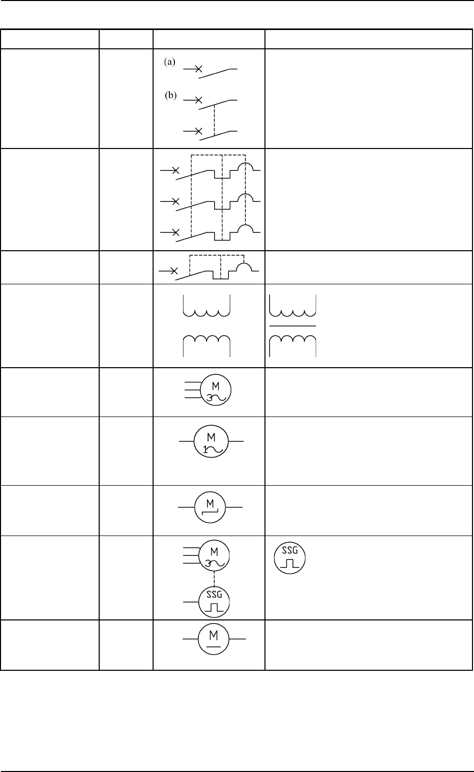
Name Symbol Graphic Symbols Remarks
Air-Break Switch
Breaker Q*
Circuit Breaker Q*
Circuit Protector
Transformer T* Transformers with iron
cores are used in the
machine and are expressed
as shown in the left figure.
Three-Phase M*
Alternating
Current Motor
Single-Phase M*
Alternating
Current Motor
Cooling Fan MFAN*
Stepping Motor MPM*
Servomotor MSVM* The left figure shows an en-
coder.
DC Motor
0207-001 Chapter 3 3-42 Tg0699-PM-D2
4.1 Electrical and Electronic Symbols
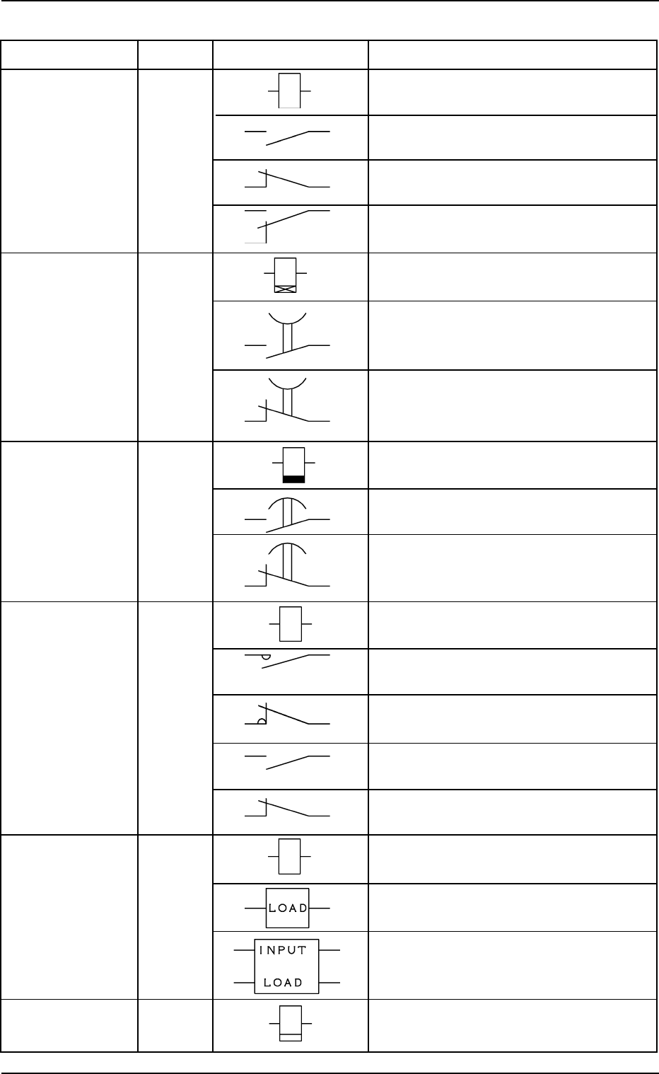
Name Symbol Graphic Symbols Remarks
Relay K* Coil
Contact a
Contact b
Contact c
Timing Relay KT* Coil
(ON Delay) (ON Delay)
Contact a
(Make Point)
Timer
Contact b
(Break Point)
Timing Relay KT* Coil
(OFF Delay) (ON Delay)
Contact a
(Make Point)
Contact b
(Break Point)
Electromagnetic KM* Coil
Contactor
Main Contact a
Main Contact b
Sub Contact a
Sub Contact b
Solid-State Relay KSSR* INPUT
LOAD
A relay may be drawn using both “INPUT
and “LOAD”.
Cycle Counter