2OM-1088-002.pdf - 第360页
Tg0699-PM-D2 0207-001 Chapter 3 1-41 9.1 Replacement of Squeegees (3) Open the "SEMI-AUTO OPN." window (submenu) or the "Print Block" tab sheet of the "MAN. SUB-SYS" window (submenu) and pus…
Tg0699-PM-D2
Ref.:
Pushing Dimension L during Upward Remarks
Distances Movement of Cylinder
0.5 mm 57.5 (58.5) mm
1.0 mm 57.5 (59.0) mm Settings when delivered.
1.5 mm 58.0 (59.5) mm
Fig. 5A56
0207-001 Chapter 3 1-40
9.1 Replacement of Squeegees
9.1.1 Adjustment of Squeegee Head Height
Adjustment Procedure
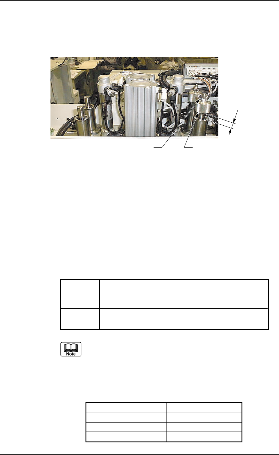
(1) Loosen the wing and stopper nuts.
Stopper Nut
Wing Nut
L
(2) Adjust the pushing distance by changing Dimension L (the
distance between the upper end plane of the ball bushing and
the lower end plane of the stopper nut).
The pushing distance of the squeegee against the screen is set
to "1.0 mm". (Factory-Adjusted upon Shipment)
When the stopper nut is turned once clockwise, the pushing
distance becomes shorter by 1.0 mm.
Turning the stopper nut once counterclockwise makes the
pushing distance longer by 1.0 mm.
Figures in brackets show the dimension L when the
following metal squeegees are used. If other types of
squeegee are used, consult with our Marketing Dept. or
agent.
Manufactured by Permalex
Model No. Part No.
PLX-A3060-270 630 111 8543
PLX-A3060-350 630 114 4184
PLX-A3060-480 630 117 8097

Tg0699-PM-D2
0207-001 Chapter 3 1-41
9.1 Replacement of Squeegees
(3) Open the "SEMI-AUTO OPN." window (submenu) or the "Print
Block" tab sheet of the "MAN. SUB-SYS" window (submenu)
and push the squeegee against the P.C.B. located in the printing
section.
Refer to the above table and check the relation between Dimen-
sion L and the pushing distance.
(a) When the rubber squeegees are worn out, the push-ing
distance becomes as short as they are worn out. There-
fore, it is required to change the rubber squeegees
before the pushing distance is changed greatly (in the
range of 0.5 mm or less).
(b) The rubber squeegees can be ground to be re-used. In
this case, the total of the dimension (grinding) is limited
to "1.5 mm" (when the maximum pushing distance is
"0.5 mm").
When the total of the dimension (grinding) has become
"1.5 mm", be sure to replace the rubber squeegees with
new ones.
(c) When the rubber squeegees are ground to be re-used,
lower the location of the stopper nuts according to the
dimensions of the ground rubber squeegees (the squee-
gees that have become shorter after grinding) so that
the same pushing distances can be kept.
Tg0699-PM-D2
Clip
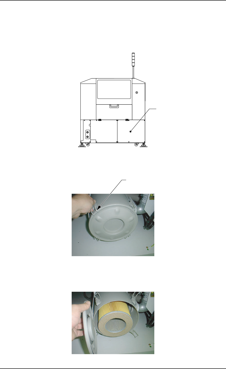
9.2 Cleaning Procedure of Blower Filter
Operation Procedure
(1) Remove the cover located at the lower part of the rear side.
(6 screws)
Fig. 5A61
(2) Disengage the clip fastening the lid of the filter cover.
(4 places)
Fig. 5A62
(3) Remove the lid.
Fig. 5A63
0207-001 Chapter 3 1-42
9.2 Cleaning Procedure of Blower Filter
Cover