2OM-1088-002.pdf - 第362页
Tg0699-PM-D2 0207-001 Chapter 3 1-43 9.2 Cleaning Procedure of Blower Filter (4) Detach the filter and remove dust accumulated on the filter with an air gun and a vacuum cleaner . Fig. 5A64 (5) Set the filter such that t…
Tg0699-PM-D2
Clip
9.2 Cleaning Procedure of Blower Filter
Operation Procedure
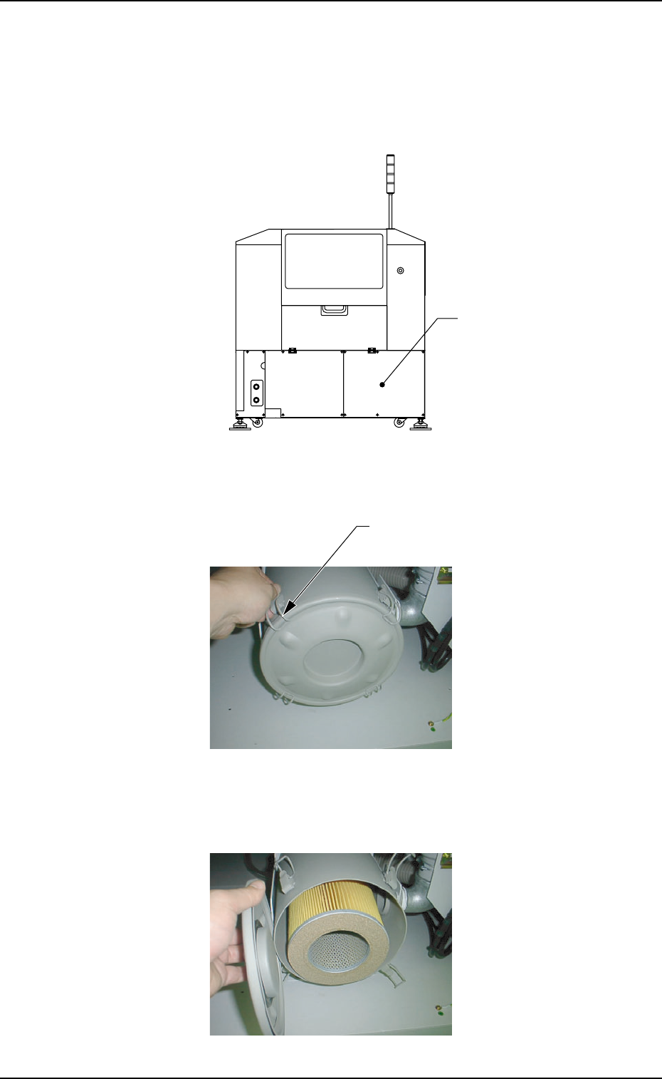
(1) Remove the cover located at the lower part of the rear side.
(6 screws)
Fig. 5A61
(2) Disengage the clip fastening the lid of the filter cover.
(4 places)
Fig. 5A62
(3) Remove the lid.
Fig. 5A63
0207-001 Chapter 3 1-42
9.2 Cleaning Procedure of Blower Filter
Cover
Tg0699-PM-D2
0207-001 Chapter 3 1-43
9.2 Cleaning Procedure of Blower Filter
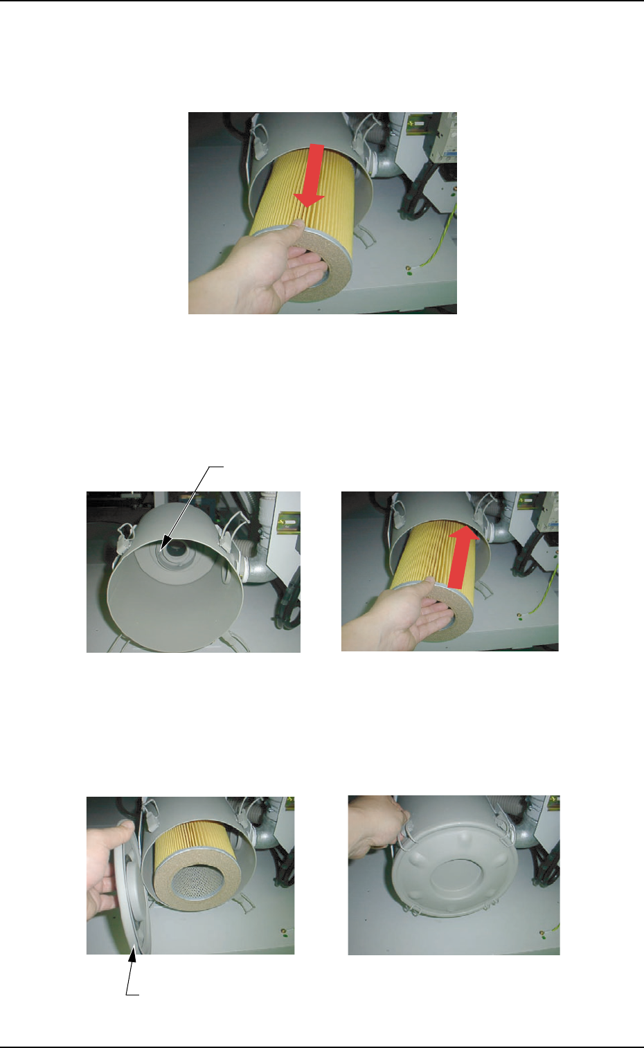
(4) Detach the filter and remove dust accumulated on the filter with
an air gun and a vacuum cleaner.
Fig. 5A64
(5) Set the filter such that the center hole of the filter can fit into the
flange located at the rear side of the filter cover.
Fig. 5A65
(6) While holding the lid, engage the clip securely such that the
flange (located at the center of the lid) can fit into the center
hole of the filter.
Fig. 5A66
Flange Section
Flange Section
Tg0699-PM-D2
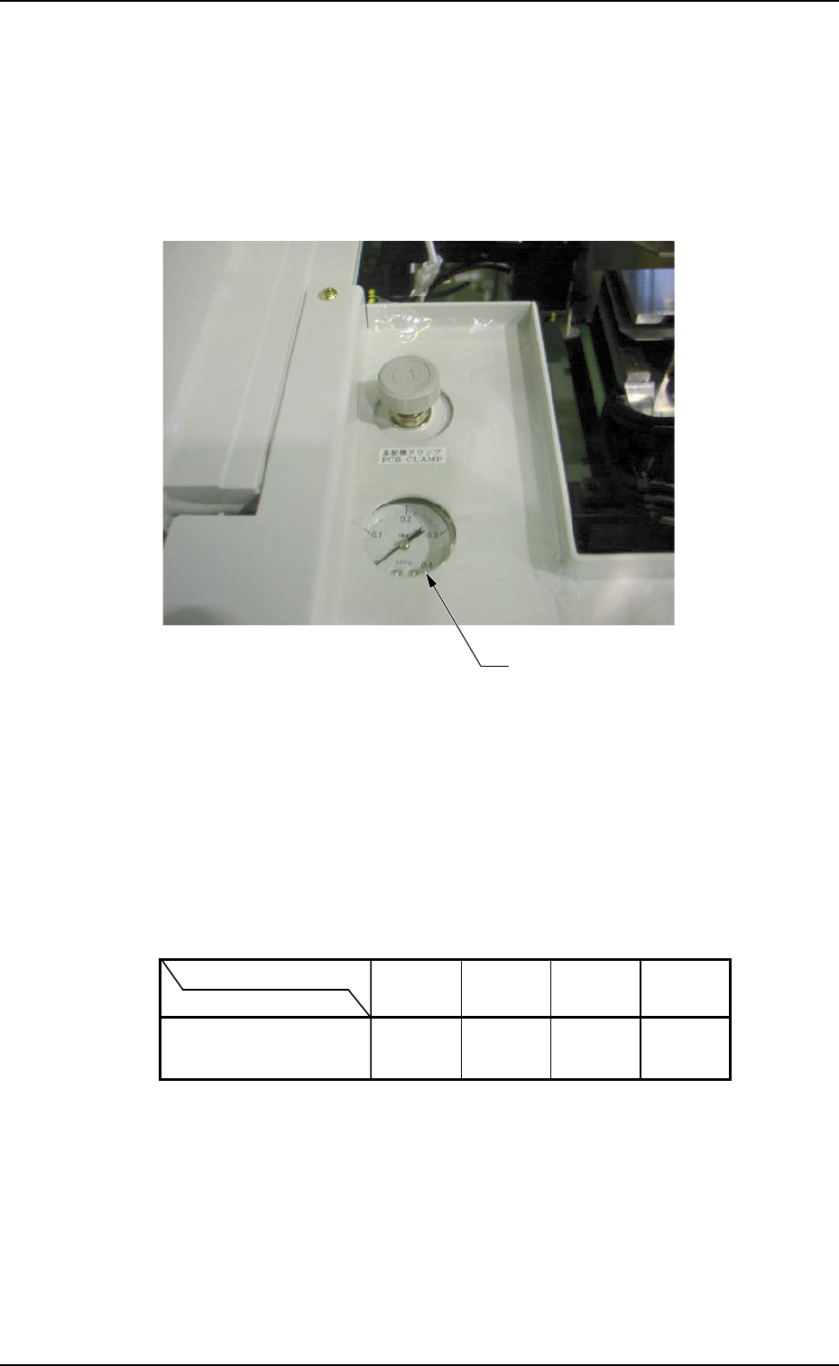
10. Adjustment of P.C.B. Horizontal Clamping
When a thin P.C.B. is used and the horizontal clamping force is
strong, it may be warped. To avoid this, adjust the force with the
pressure reducing valve which is located at the front left (operator
side) of the L conveyor.
Fig. 5A67
• Refer to the following table for the relation between the P.C.B.
thickness and air pressure.
The values indicate the pressures to be applied, assuming that a
P.C.B. (Dimensions: "150 × 100") is used without a P.C.B. stopper.
0207-001 Chapter 3 1-44
10. Adjustment of P.C.B. Horizontal Clamping
Pressure Reducing Valve
P.C.B. Thickness
Air Pressure
MPa
(kgf/cm
2
)
0.12
(1.2)
0.2
(2.0)
0.3
(3.0)
0.3
(3.0)
0.5 mm 1.0 mm 1.5 mm 2.0 mm