2OM-1088-002.pdf - 第62页
Tg0699-PM-D2 1.2 Operation Data 0207-001 Chapter 1 2-3 (2) P .C.B. Origin Offset X (horizontal) and Y (vertical) Set the offset values to correct the dif ference between the reference point (N 0 ) of the pattern program …
Tg0699-PM-D2
1. Pattern Program
0509-002 Chapter 1 2-2
1. Pattern Program
1.1 Pattern Program Name
When a pattern program should be saved, alphanumerics and sym-
bols can be used as a pattern program name.
(a) If a long name is set in the "Pattern Program Name"
data box, the last letters might not be displayed in the
window. Please confine the name to 24 letters or less, if
possible.
(b) The following symbols cannot be used in pattern pro-
gram names.
* (asterisk), ? (question mark), : (colon), " (double quota-
tion mark), / (slash), | (vertical line), < (smaller than), >
(larger than), , (comma), . (period)
(c) Note that "," (comma) cannot be used in "Comment"
data box either.
1.2 Operation Data
1.2.1 P.C.B. Data
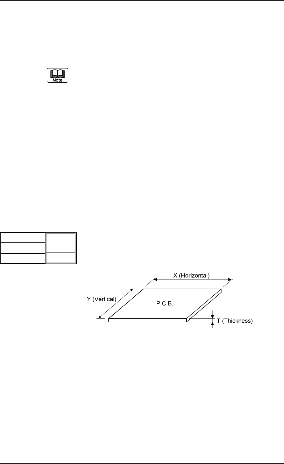
(1) P.C.B. Size
X (horizontal), Y (vertical), and T (thickness)
Set the dimensions of the P.C.B. to be produced.
Unit : mm
2.00
X
Y
000.00
000.00
T
Fig.3B1
Fig. 3B2
Data Input Range
X : 50 to 460 Y : 50 to 381 T : 0.5 to 5.0
Tg0699-PM-D2
1.2 Operation Data
0207-001 Chapter 1 2-3
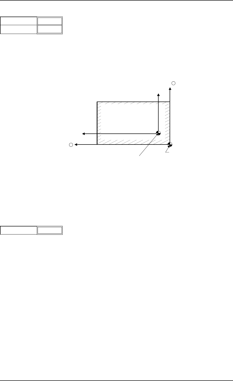
(2) P.C.B. Origin Offset
X (horizontal) and Y (vertical)
Set the offset values to correct the difference between the
reference point (N
0
) of the pattern program and the P.C.B.
origin (P
0
) .
Unit : mm
"Plus" and "Minus" offset values can be set for correction on
both the X and Y coordinates.
Fig. 3B4 Example of Correction in "+" (plus) Direction
Data Input Range
X : -99.999 to +99.999 Y : -99.999 to +99.999
(3) Operation Mode
It can be selected whether or not solder paste should be
printed on the P.C.B. to be produced.
PRINT : The machine prints solder paste during automatic
operation.
PASS : The machine performs only P.C.B. transfer during
automatic operation.
X
Y
+00.000
+00.000
Fig.3B3
P
0
(P.C.B. Origin)
Y +
X +
P.C.B.
N
0
(Printing Coordinates Reference)
Operation Mode Print
Fig.3B5
Tg0699-PM-D2
1.2 Operation Data
0207-001 Chapter 1 2-4
Screen Center
S
o
S
o
Squeegee
L2
X2
(-)
P.C.B.
Pattern
Program
Origin
L1
X2
(+)
Origin
Depth
+ 000.00
+ 000.00
Fig.3B6
(4) Print Area
Set parameters as offset values of the P.C.B. end plane in the
Y direction.
Unit : mm
Enter the offset values based on the pattern program
coodinates of the end planes on the origin and rear sides.
When the defaults "0" (zero) are set, the whole area of the
P.C.B. is printed.
Various offsets are considered in the actual printing range as
shown below.
Fig. 3B7
L1, L2 : Printing Area Data (based on the pattern program
origin)
X2 : Overshoot at End of Printing
So : Travel from Previous End Position at Printing Start
(Squeegee Offset)
Data Input Range
Origin Side : -10 to +381
Rear Side : -381 to +10