2OM-1088-002.pdf - 第453页
4. Electrical Circuit Diagrams 4.1 Electrical and Electronic Symbols Name Symbol Graphic Symbols Remarks Grounding (General) Protective Ground Connection (Chassis) Cable W* “W*” is used only for signal wires in block dia…
Tg0699-PM-D2
3.7 Location of Sensors and Loads in Cleaning Section/Air Blow Section (Option)
0207-001 Chapter 3 3-38-22
Table 5C9
Symbols Name
BPS080 Cleaning Nozzle U/D Upper Limit
BPS081 Cleaning Nozzle U/D Lower Limit
BPH082 Paper Feed Pitch Detection
BPX083 Solvent Shortage Alarm
BPH084 Paper Shortage Alarm
BPH094 Cleaning Unit Detection
BPS095 Cleaning Unit Clamping
BPS120 Air Blow Fluctuation Output Side
BPS121 Air Blow Fluctuation Return Side
M009 Cleaning Paper Supply Motor
BPS090 Cleaning Suction Side
BPS091 Cleaning Suction Standby Side
BPS092 Chuck Suction Side Air Blow Fluctuation (Return Side)
BPS093 Chuck Section Standby Side
YSV098 Cleaning Suction Solenoid Valve
YSV099 Chuck Suction Solenoid Valve
YSV088 Nozzle Up Movement Solenoid Valve
YSV089 Nozzle Down Movement Solenoid Valve
YSV08A Solvent Discharge Solenoid Valve
YSV128 Air Blow Fluctuation Solenoid Valve
YSV129 Air Blow Solenoid Valve
4. Electrical Circuit Diagrams
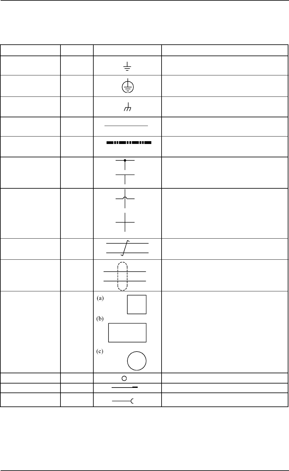
4.1 Electrical and Electronic Symbols
Name Symbol Graphic Symbols Remarks
Grounding
(General)
Protective Ground
Connection
(Chassis)
Cable W* “W*” is used only for signal wires
in block diagrams.
Optical Fiber
Cable
Connection The cables are connected electrically.
No Connection The cables are not connected electrically.
Twisted Pair Signal wires are twisted.
Shielded Shielded Wires
(Shielded Wires)
Equipment or
Device
Terminal
Plug X*
Jack Socket X*
0207-001 Chapter 3 3-39 Tg0699-PM-D2
4. Electrical Circuit Diagrams
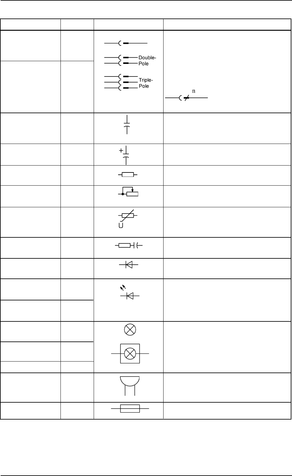
Name Symbol Graphic Symbols Remarks
Combination of X* X* : Connectors and Power Outlets
Plug and Jack for External Connections
Connector XCN* XCN*: Connectors for Internal Connec-
Nylon Connector XNC* tions
XNC*: Nylon Connectors for Relay
The left figure shows a
connector with multipoles.
“n” is the number of poles
Electrostatic C*
Capacity or
Capacitor
Capacitor
(Polarity)
Resistance or R*
Resistor
Variable Resistor RVR*
Voltage-Depen-
dent Resistor or
Varister
Surge Killer
Diode HA* “D*” is sometimes used for diodes in a
unit P.C.B.
Light Emitting The graphical symbol (light emitting
Diode (General) diode) is used to represent the light
Indicator Lamp HD* emitting diodes in illuminating switches
and indicator lamps
Indicator Lamp H* This represents a general electric lamp
HPL* used in an indicator lamp, an indicator,
Recognition EL* etc.
Lighting
Lighting Device E*
Buzzer HA*
Fuse F*
0207-001 Chapter 3 3-40
Tg0699-PM-D2
4.1 Electrical and Electronic Symbols