2OM-1088-002.pdf - 第487页
Tg0699-PM-D2 Relay Circuit Diagram 2 0207-001-(M782WRG--0002) Chapter 3 3-71 Relay Circuit Diagram 2 T ransformer SCB T ransformer PCB T able Z-Axis CB V acuum Pump CB CB Alarm Monitor Load Power ON Power Supply for Load…
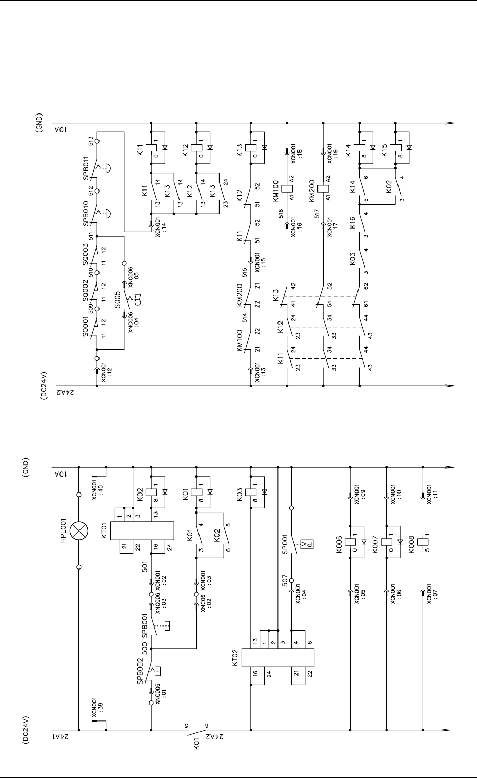
Tg0699-PM-D2
Relay Circuit Diagram 1
0207-001-(M782WRG--0001) Chapter 3 3-70
Relay Circuit Diagram 1
Power OFF
Power ON
Air Pressure Detection
Power Indicator
Power ON Delay
Power Supply
Air Pressure
Drop Monitor
200 V AC Control
Power Supply
100 V AC Control
Power Supply
SDS Bus
Power Supply
Safety Door
(Front Side)
Safety Door
(Rear Side)
Safety Door
(Cleaning Section)
OPERATION/SET UP
Air Pressure
Monitor
CB Alarm
Monitor
Power ON Delay
Safety Relay 1
Safety Relay 2
Safety Relay 3
100 V AC Power Supply
200 V AC Power Supply
Load Power Monitor 1
Load Power Monitor 2
Emergency Stop
(Front Side)
Emergency Stop
(Rear Side)
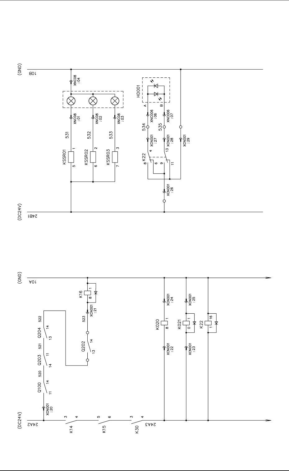
Tg0699-PM-D2
Relay Circuit Diagram 2
0207-001-(M782WRG--0002) Chapter 3 3-71
Relay Circuit Diagram 2
Transformer
SCB
Transformer
PCB
Table
Z-Axis CB
Vacuum Pump CB
CB Alarm Monitor
Load Power ON
Power Supply
for Loads 100V AC
Full Load Power Monitor
Red
Yellow
Red Green
Orange
Green
Tower Light, Red
Tower Light, Yello
w
Tower Light, Green
Power ON Indicator
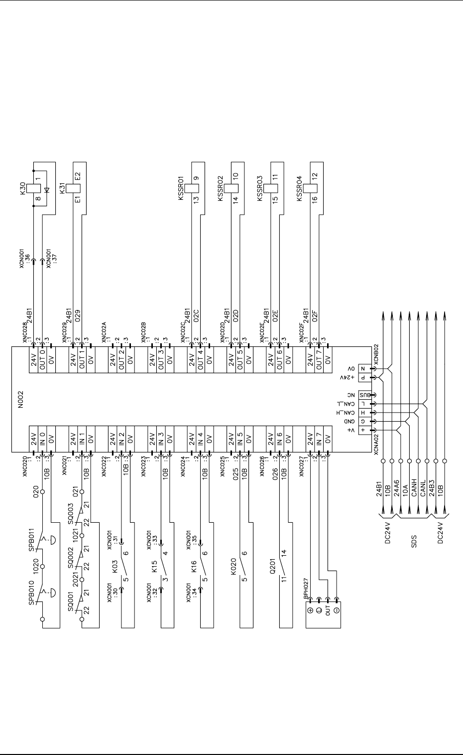
Tg0699-PM-D2
Relay Sequence Section I/O
0207-001-(M782WRG--0003) Chapter 3 3-72
Relay Sequence Section I/O
Bus
Load Power OFF
Tower Light, Red
Tower Light, Yellow
Tower Light, Green
Empty
Power Supply to Table Z-Axis
Main Circuit
Emergency Stop Monitor
Safety Door Monitor
Air Pressure Drop Monitor
Load Power Monitor
C.B Alarm Monitor
Lightning Surge
Protection Monitor
Load Power ON
Calibration I. L