2OM-1088-002.pdf - 第484页
Tg0699-PM-D2 Power Circuit Diagram 2 0207-001-(M782WRE--0002) Chapter 3 3-68 Power Circuit Diagram 2 Lighting SW Power Supply to Console Lighting for Operation Power Supply to Panel Computer Power Supply to Interface Int…
Tg0699-PM-D2
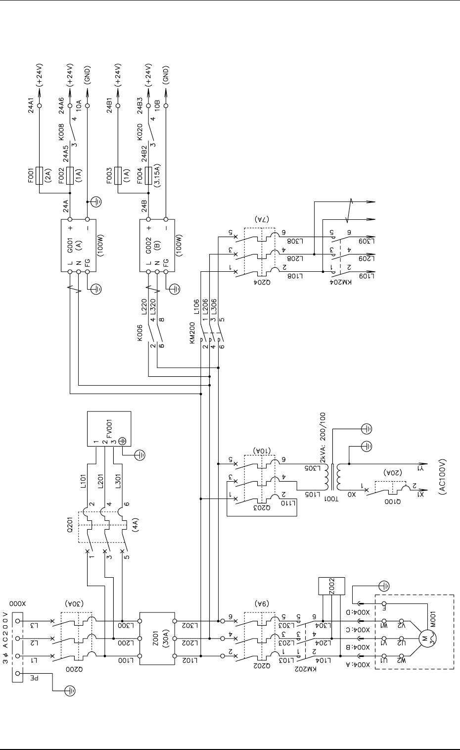
Power Circuit Diagram 1
0207-001-(M782WRE--0001) Chapter 3 3-67
Power Circuit Diagram 1
Vacuum Pump
Lightning Surge Absorber
Table Z-Axis
Servo Power Supply
Relay Power Supply
Sensor Power Supply
Tg0699-PM-D2
Power Circuit Diagram 2
0207-001-(M782WRE--0002) Chapter 3 3-68
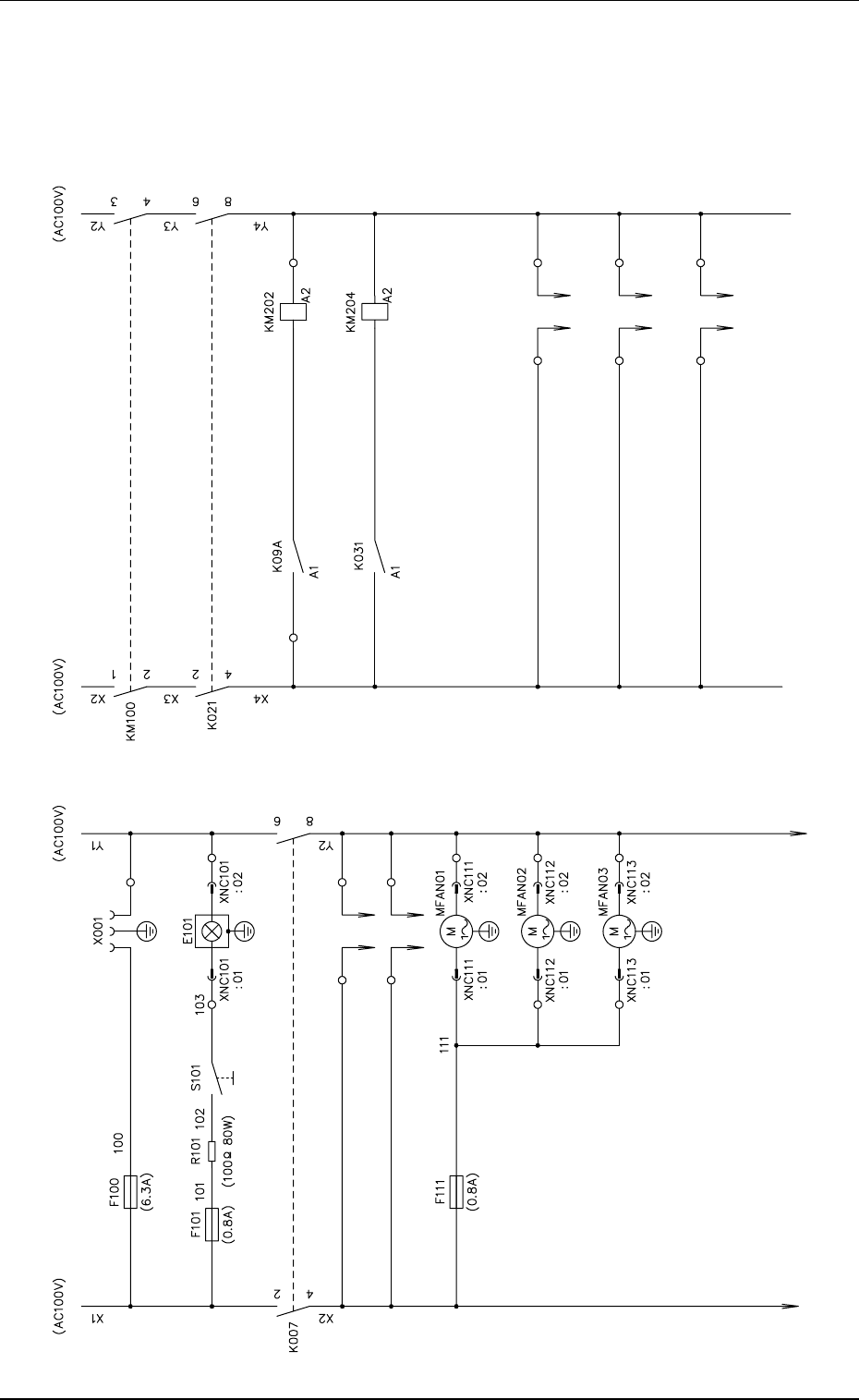
Power Circuit Diagram 2
Lighting SW
Power Supply
to Console
Lighting for
Operation
Power Supply
to Panel Computer
Power Supply
to Interface
Interface Fan 1
Interface Fan 2
Interface Fan 3
Vacuum Pump Driving
Table Main Circuit
Power Supply
to Pulse Motor
Power Supply
to Conveyor
Power Supply
to Cleaning Section
Tg0699-PM-D2
0207-001-(M782WRF--1003) Chapter 3 3-69
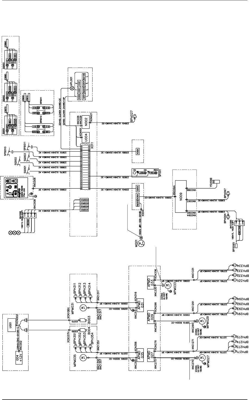
Mechanical Distribution Section 3
Mechanical Distribution Section 3
Control Box
Recognition
P.E.C. Recognition Section
P.E.C.
Recognition
X-Axis
Screen
Recognition
X-Axis
Squeegee Head Section
Driver 2 Section
Green/Yellow
Green/Yellow
Green
/Yellow
Squeegee
Driving Axis
Screen
Y-Axis
P. E .C .
Recognition
Y-Axis
White Black
White
Red
Gray Black
Utility Section
Vacuum Pump
Section
Cleaning Section
Power Supply Section
Gray
Yellow
Orange
White
Gray
Yellow
Orange
White
Gray
Yellow
Orange
White
White
White
Orange
Orange
Yellow
Yellow
Gray
Gray
Operation Panel Section
Relay Sequence
Section
Red
Orange
Green
Yellow
Tower Light
Air Pressure
Detection
Attachment of
Two Ferrite Cores
Connector No. Connector No.
23640:Camera Cable(SHC-01109-1)
23640:Camera Cable(SHC-01109-1)
Attached Cable
Connector No.