2OM-1088-002.pdf - 第65页
Tg0699-PM-D2 (6) Squeegee Spd. Select the speed at which the squeegees move back and forth for printing. Unit : mm/s For . : Set the speed at which the squeegees move forward (from the rear to the front side). Back. : Se…
Tg0699-PM-D2
0207-001 Chapter 1 2-5
1.2 Operation Data
1.2.2 Print Data
(1) Screen Basis
Select a reference type of the screen frame.
Center Ref. : The center of the screen frame is regarded as a
reference point.
Front Ref. : The front side of the screen frame is regarded
as a reference point.
Rear Ref. : The rear side of the screen frame is regarded
as a reference point.
(2) Round-Way Printing
It can be selected whether or not the round-way printing opera-
tion should be performed.
ON : The machine performs the round-way printing opera-
tion.
OFF : The machine does not perform the round-way printing
operation.
(3) Frame Select
Select dimensions of the screen frame to be used.
Uni t: mm
736
××
××
×736 550
××
××
×550 720
××
××
×720 650
××
××
×550
600
××
××
×550 550
××
××
×650 750
××
××
×650 650
××
××
×750
(4) Prntg. Press.
Set the printing pressures of the front and rear squeegees.
Unit : N
Data Input Range : 9 to 200
If the same solder paste is used for a long time, vis-
cosity might increase, causing printing error. To pre-
vent that, we recommend setting the printing pressure
as high as possible, enabling printing without hin-
drance.
(5) Squeegee Select
Select the length of squeegee to be used.
Unit : mm
270 350 480
Front Side
Rear Side
040
040
Fig.3B11
Fig.3B8
Screen Basis
Center Ref.
Round-Way Printing
OFF
Fig.3B9
Frame Select
650
××
××
×
550
Fig.3B10
Squeegee Select
350
Fig.3B12
Tg0699-PM-D2
(6) Squeegee Spd.
Select the speed at which the squeegees move back and forth
for printing.
Unit : mm/s
For. : Set the speed at which the squeegees move forward
(from the rear to the front side).
Back. : Set the speed at which the squeegees move back-
ward (from the front to the rear side).
(7) Screen Distance
Set the clearance between the screen and the upper surface
of the P.C.B. during printing operation.
Unit : mm
Data Input Range : -1.5 to 3.0
(8) Separation Mode
Set a parameter to determine whether or not the squeegees
must move up after the P.C.B. has descended or the P.C.B.
must move down after the squeegees have ascended when
the screen frame is separated from the P.C.B. after the
completion of printing.
Select "PCB Down" in normal cases.
PCB Down : The squeegees move up after the P.C.B. has
descended.
Squeegee Up : The P.C.B. moves down after the squeegees
have ascended.
(9) Separation Speed
Set the speed at which the screen frame should be separated
from the P.C.B. after the end of printing.
Unit : mm/s
Data Input Range : 0.05 to 3.00
(10) Separation Acc.
Set the acceleration rate at which the screen frame should be
separated from the P.C.B. after the end of printing.
Unit : mm/s
2
Data Input Range : 0.1 to 50.0
Screen Distance
-0.1
Fig.3B14
1.2 Operation Data
0207-001 Chapter 1 2-6
Separation Acc. [mm/s
2
]
50.00
Fig.3B17
Separation Speed [mm/s]
0.05
Fig.3B16
Separation Mode PCB Down
Fig.3B15
005
005
FOR.
BACK
Fig.3B13
Tg0699-PM-D2
1.2 Operation Data
0207-001 Chapter 1 2-7
(11) Separate Distance
Set the distance of the screen frame to be kept when it is
separated from the P.C.B. after the end of printing.
Unit : mm
Data Input Range : 0 to 9.9
(12) Prntng. Correction (Back)
X [mm], Y [mm],
θθ
θθ
θ [ °
]
Set parameters to correct the relative position (trace quantity)
between the P.C.B. and the screen kept when the squeegees
move backward (from the front to the rear side).
(13) Prntng. Correction (For.)
X [mm], Y [mm],
θ θ
θ θ
θ [ ° ]
Set parameters to correct the relative position (trace quality)
between the P.C.B. and the screen kept when the squeegees
move forward (from the rear to the front side).
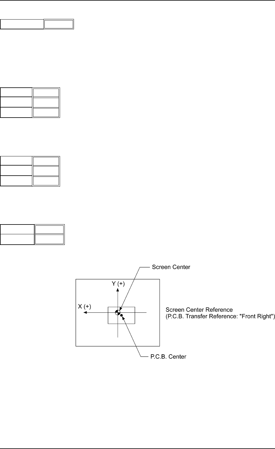
(14) Screen Offset [mm]
When the reference coordinates of the screen are changed
from the design values, set parameters as the offset values.
Unit : mm
X
Y
Fig.3B21
+ 0.0
+ 00.0
Separation Distance [mm]
0.5
Fig.3B18
X [mm]
Y [mm]
+ 0.000
θ [ ° ]
+ 0.000
+ 0.000
Fig.3B20
X [mm]
Y [mm]
+ 0.000
θ [ ° ]
+ 0.000
+ 0.000
Fig.3B19
Fig. 3B22
Data Input Range
X : ±5.0
Y : ±99