2OM-1088-002.pdf - 第393页
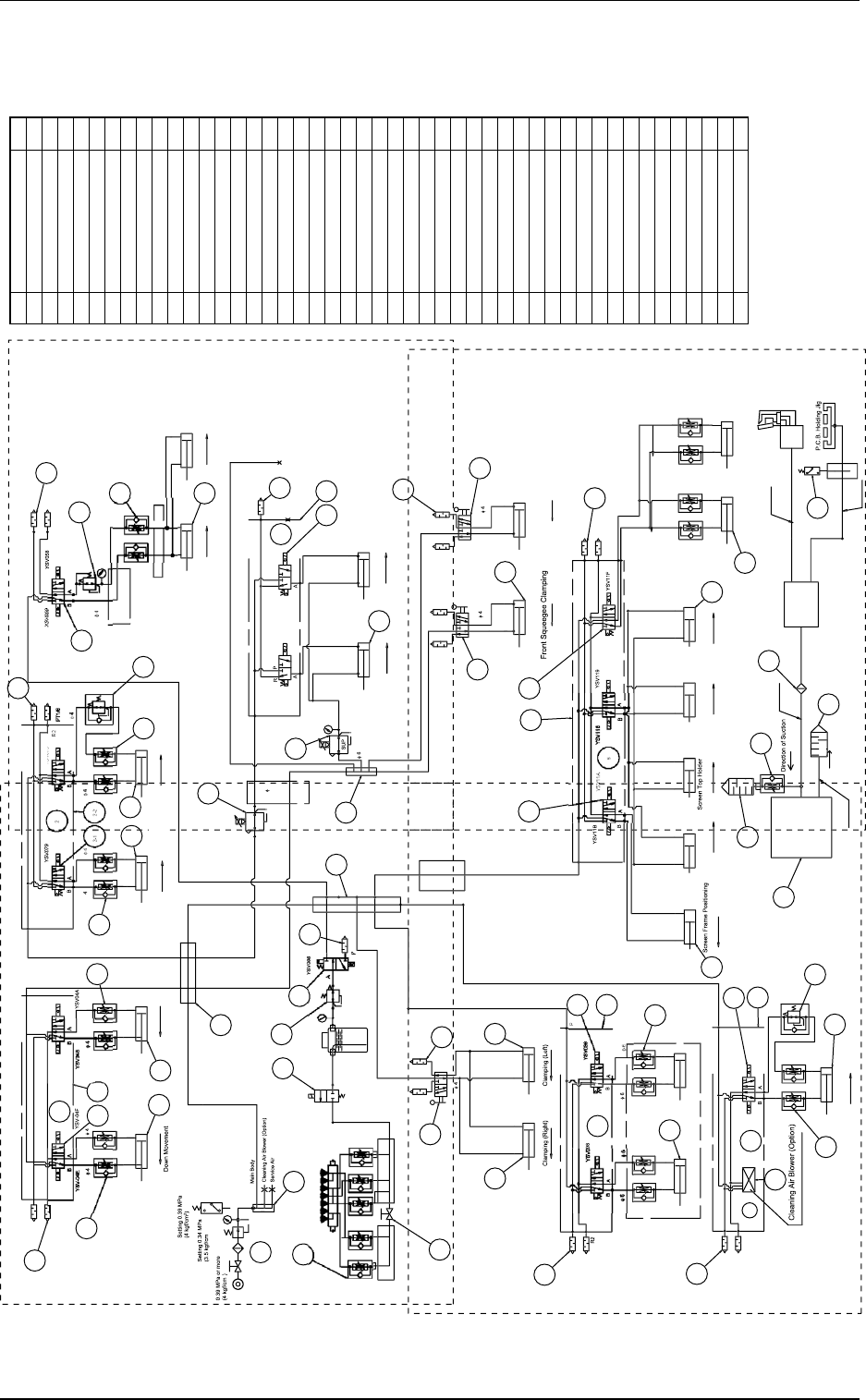
Tg0699-PM-D2 1. Pneumatic Diagrams 0207-001-(M782XA---0002) Chapter 3 3-2 1. Pneumatic Diagrams A B C D 30 3 1 3 2 33 3 4 3 7 3 7 3 7 38 4 1 40 39 4 1 41 5 2 35 36 R Conve y or Section L Conve y or Section φ 4 P.C.B. Sto…

Tg0699-PM-D2
Section 3
Material
This section describes the pneumatic diagrams, the parts
location, the location of sensors and loads, the electrical
circuit diagrams, etc.
As this section contains highly sophisticated contents, it
should carefully be referred to.
0207-001 Chapter 3 3-1
Tg0699-PM-D2
1. Pneumatic Diagrams
0207-001-(M782XA---0002) Chapter 3 3-2
1. Pneumatic Diagrams
A
B
C
D
30
3
1
3
2
33
3
4
3
7
3
7
3
7
38
4
1
40
39
4
1
41
5
2
35
36
R
Conve
y
or Section
L
Conve
y
or Section
φ
4
P.C.B. Stopper
on Conveyor
Up
Movement
P
.C.B. Sto
pp
er
on Conveyor
Up
Movement
P
.C.B. Sto
pp
er
Up Movement
p
P.C.B. Holding
41
42
43
44
45
46
46
47
48
49
50
1
-1
1
-
2
1
3
4
4
-1
4
-2
5
-1
5
-2
5
-
3
6
6
-1
6
-2
7
7
-1
7
-
2
5
1
5
1
8
9
10
10
1
0
1
1
1
2
13
14
15
16
17
1
8
19
20
2
1
2
2
23
24
X2
X
2
X2
X4
X2
X2
25
25
25
26
27
28
29
19
D
uc
t
Loc
k
Loc
k
Screen Lock
(Front)
C
leanin
g
Unit
50
D
uc
t
D
ir
ec
ti
o
n
o
f Exh
aus
t
Loc
k
Loc
k
Vacuu
m
Suc
ti
o
n
Sec
t
o
n
C
leanin
U
nit
V
acuum
S
uction
S
ection
S
creen Holder
S
ection
C
h
uc
k
Sec
ti
o
n
3
2 D
uc
t
50
D
uc
t
B
lower Unit Chan
g
eover Section
B
lower Unit Chan
g
eover Section
φ
6
φ
6
φ
8
φ
1
0
φ
4
φ
6
φ
6
φ
4
φ
4
43
φ
4
φ
6
φ
YS
V
089
YS
V
088
YS
V
08
A
YSV078
Cab
l
e
Bea
r
e
r
C
h
uc
k
Suc
ti
o
n
C
reanin
g
Suction
R1
R
2
R
1
P
C
leanin
g
Unit
Loc
k
C
leanin
g
Unit
φ
6
6
φ
6
Cab
l
e
B
ea
r
ee
C
able Bearee
φ
1
0
P
T1
/8
R1
P
P
.C.B. Chuck
(
Front Side
)
C
huck Backward Movement
P
.C.B. Chuck
(
Front Side
)
C
huck Backward Movement
C
leanin
g
Up/Down
(
Front
)
P
R1
R
2
R1
R2
φ
6
EXH
OU
T
SU
P
P
ositionin
g
MS
-
5
P
φ
4
φ
4
φ
4
φ
4
φ
4
φ
6
φ
φ
6
φ
6
φ
6
Y
SV069
YS
V
068
OU
T
EXH
φ
4
F
ront Squee
g
ee Up/Dowen
φ
6
R
1
P
Up
Movement
R
ear Squee
g
ee Up/Dowen
Up
Movement
Loc
k
φ
4
Loc
k
R
ear Squee
g
ee Clampin
g
S
creen To
p
H
older
(
Left Side
)
Loc
k
Loc
k
S
creen To
p
Holder
(
Ri
g
ht Side
)
Loc
k
S
creen To
p
H
older
(
Ri
g
ht Side
)
Loc
k
φ
6
φ
6
φ
6
φ
1
0
Do
wn M
o
v
e
m
e
nt
1
1
2
2
1
1
2
2
1
1
1
1
2
2
1
1
2
8
2
2
4
1
3
2
4
1
1
1
1
5
1
1
2
2
2
1
2
2
2
1
2
1
1
1
1
1
No.
1
2
3
4
5
6-1
6-2
7
8
9
10
11
12
13
14
15-1
15-2
16
17
18
19
20
21
22
23
24
25
26
27
28
29
30
31
32
33
34-1
34-2
35
36
37
38
39
40
41
42
43
Q'ty
Name
Combination Unit
Solenoid Valve
Silencer
Speed Controller
Air Cylinder
Manifold
Solenoid Valve
Silencer
Air Cylinder
Air Cylinder
Solenoid Valve
Precision Pressure Reducing Valve
Speed Controller
Air Cylinder
Electropneumatic Regulator
Manifold
Solenoid Valve
Silencer
Air Cylinder
Air Cylinder
Speed Controller
Solenoid Valve
Mechanical Valve
Air Cylinder
Air Cylinder
Solenoid Valve
Precision Pressure Reducing Valve
Solenoid Valve
Valve
Speed Controller
Air Cylinder
Solenoid Valve
Speed Controller
Silencer
Air Cylinder
Manifold
Solenoid Valve
Silencer
Speed Controller
Blower
Silencer
Speed Controller
Air Filter
Power Switch
Joint
Joint
2
)
2
P.C.B. Recognition
.
R
S
ection
(
Left Sid
e
e)
Air
Sou
r
ce
in Pr
o
fl
o
w in
s
t
a
ll
a
ti
o
n
(
Standard condition is that hose is folded
)
.
(
Vertical
)
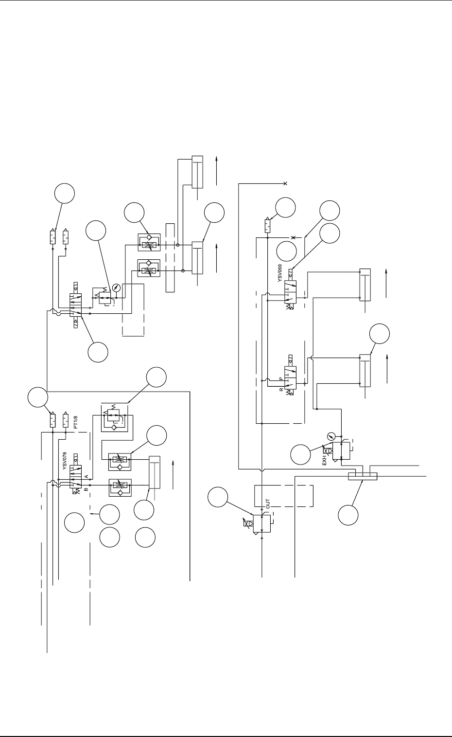
Tg0699-PM-D2
Pneumatic Diagram (Details A)
0207-001-(M782XA---0002) Chapter 3 3-3
Pneumatic Diagram (Details A)
30
3
1
3
2
37
38
39
36
47
2
-
1
2
-
2
2
3
4
4
-
1
4
-
2
13
14
15
16
X
2
X2
26
27
Up
Movement
P
.
C
.B.
C
huck
S
ection
φ
4
φ
4
φ
4
φ
4
φ
6
Cab
l
e
B
ea
r
e
r
Cab
l
e
B
ea
r
e
r
P
.C.B. Holdin
g
R2
R1
YS
V
058
YS
V
059
P
.C.B. Chuck
(
Front Side
)
C
h
uc
k B
ac
kw
a
r
d
M
o
v
e
m
e
nt
P
.C.B. Chuck
(
Front Side
)
C
h
uc
k B
ac
kw
a
r
d
M
o
v
e
m
e
nt
R1
R2
A
B
EXH
SU
P
MS
-
5
P
φ
4
A
φ
4
φ
4
φ
4
φ
4
φ
6
φ
6
φ
6
φ
6
YS
V
068
SU
P
OU
T
F
ront Squee
g
ee Up/Down
φ
6
R1
P
A
Up
Movement
R
ear Squee
g
ee Up/Down
Up
Movement
P
.E.C. Reco
g
nition Section
A
ir
Sou
r
ce
in Pr
o
fl
o
w in
s
t
a
ll
a
ti
o
n
(
Standard condition is that hose is folded
)
.